background image

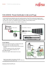
3.3.2. BatteryProtect remote on/off switch

The below example shows a BatteryProtect in a simple system with a remote on/off switch wired to the remote terminals.

This switch can be used, for example, to turn the system remotely on and off. The power consumption of the BatteryProtect is
negligible at less than 1mA when switched off (check the 

Specifications chapter

).

DC loads

System 

on/off 

switch

BatteryProtect with remote on/off switch

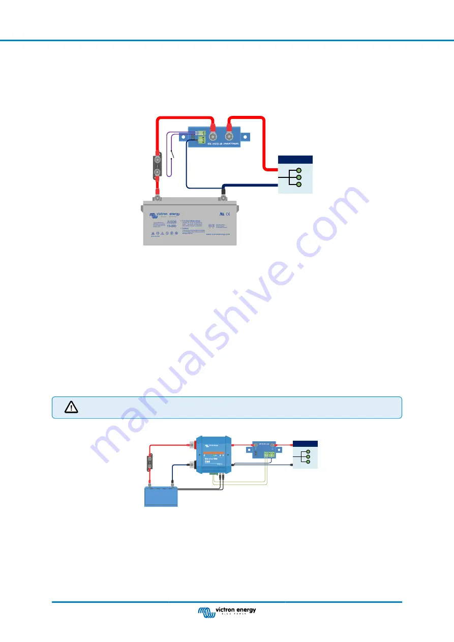
3.3.3. BatteryProtect in a lithium battery system with external BMS

The image below shows a BatteryProtect in a lithium battery system with external BMS. The external BMS (

Victron Lynx Smart

BMS

 in this example) has an ATD (allowed to discharge) and ATC (allowed to charge) output. Designed as a dry contact, ATD

and ATC function as a switch that directly controls the BP via its remote terminal.

For this, the BatteryProtect must be programmed to Li-ion mode.

The dry contact is wired between the L and H connectors of the remote terminal.

If, for example, ATD opens in the event of a lithium battery cell undervoltage, the BP will immediately disconnect the load without
delay.

The BP will remain disengaged for 30 seconds, even if ATD closes within this period. After this 30 seconds, it responds
immediately and connects the load to the battery.

Please note that the under voltage thresholds and alarm output of the BP are inactive in this mode.

If you have a lithium battery with internal BMS (so-called drop-ins) that does not have an output for controlling
loads or chargers, the BP must be programmed in mode A or B. Mode C is not applicable in this case.

DC loads

BMS cables

ATD (allowed to discharge)

Lynx Smart BMS

Fuse

BP-65

BatteryProtect in Li-ion mode controlled by ATD from a Lynx Smart BMS

BatteryProtect 12/24V

Page 6

Installation and wiring examples

Summary of Contents for battery protect BP 100

Page 1: ...BatteryProtect 12 24V 12 24V 65A 12 24V 100A 12 24V 220A rev 00 08 2022 ENGLISH...

Page 2: ...3 3 4 BatteryProtect in a lithium system with external BMS and load disconnect output 7 3 3 5 Two BatteryProtects for load and charger control 8 3 3 6 BatteryProtect Alarm output wiring 8 4 Operation...

Page 3: ...remote on off port to protect from over voltage Compared to the Smart BatteryProtect the BatteryProtect must be programmed via the PROG pin to GND pin method The BatteryProtect is a uni directional d...

Page 4: ...nt in case of Li ion batteries especially after low voltage shutdown Over voltage protection To prevent damage to sensitive loads due to over voltage The load is disconnected whenever the DC voltage e...

Page 5: ...uit protection of the BP will be activated if you try to directly connect loads with capacitors for example inverters or inverter chargers on their DC inputs For that use case please use the BP to con...

Page 6: ...inverter charger via a BP you must use the BP to control the inverter or inverter charger via its remote port See example below Note that the image shown below is an example for all BatteryProtect mod...

Page 7: ...the load after 90 seconds automatically DC loads BatteryProtect in a simple system with wire loop between L and H input factory default The same example below This time the switch is wired between bat...

Page 8: ...s the BP via its remote terminal For this the BatteryProtect must be programmed to Li ion mode The dry contact is wired between the L and H connectors of the remote terminal If for example ATD opens i...

Page 9: ...when there is an actual low cell voltage and the BP will disconnect the load and remains off for 30 seconds even if it receives a restart signal H becomes high again within this period After this 30...

Page 10: ...of the BPs always follow the current flow from IN to OUT The positive terminal of the charger goes to the IN input of the BP DC loads BP 65 charge disconnect BP 65 load disconnect Two BatteryProtects...

Page 11: ...l disconnect the load after 90 seconds and the relay will disengage In case of over voltage the load will be disconnected immediately and the alarm output will remain inactive Overvoltage trip levels...

Page 12: ...re is a connection between the PROG pin and the GND pin the 7 segment display will first step through the shutdown and restart voltage combinations as indicated by the numbers 0 9 see the Programming...

Page 13: ...ehavior This section describes the behaviour of the BatteryProtect when it is controlled via the remote on off input and when a short circuit has been detected The BatteryProtect will connect the load...

Page 14: ...roof Load disconnect delay 90 seconds immidiate if triggered by a BMS Load reconnect delay 30 seconds Default thresholds Disengage 10 5 V or 21 V Engage 12 V or 24 V Operating temperature range Full l...

Page 15: ...re 1 Confirm that the load current draw does not exceed the BP current rating 2 Check for loose high resistance connections and ensure that appropriate gauge wiring is used in the installation 3 Do no...

Reviews: