background image

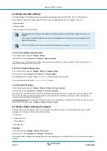
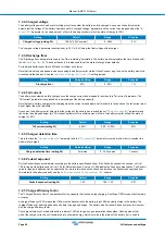
Setting

Default mode

Modes

Description

CHRG

Charger mode.

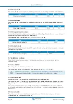
The relay will close when the state of charge
falls below setting 16 (discharge floor) or when
the battery voltage falls below setting 18 (low
voltage relay). The relay will be open when the
state of charge is higher than setting 17 (clear
state of charge relay) and the battery voltage is
higher than setting 19 (clear low voltage relay).

An application example is to start and stop
control of a generator, together with settings
14 and 15.

REM

Remote mode.

The relay can be controlled via the VE.Direct
interface. Relay settings 12 and 14 up to 31
are ignored as the relay is under the full control
of the device connected via the VE.Direct
interface.

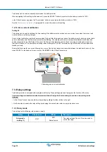
7.3.2. Invert relay

This function enables selection between a normally de-energised (contact open) or a normally energised (contact closed) relay.

When inverted, the open and closed conditions as described in all the relay settings are inverted (with the exception of the 

Relay

state [27]

).

Note that the "normally energised" setting will slightly increase the power consumption of the battery monitor.

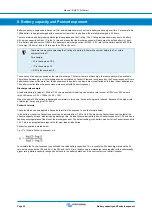
Setting

Default mode

Modes

Range

Invert relay (setting 12)

OFF

OFF

Normally de-energised

ON

Normally energised

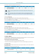
7.3.3. Relay state

This is a read-only parameter and it displays whether the relay is open or closed (de-energised or energised).

Setting

Value

Description

Relay state (setting 13)

OPEN

The relay is open (de-energised)

CLSD

The relay is closed (energised)

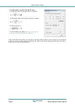
7.3.4. Relay minimum closed time

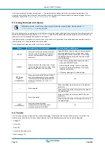
Sets the minimum time the "closed" condition will remain present after the relay has been energised.

Note that this changes to "open" and de-energised if the relay function has been inverted (

Invert relay [27]

 setting).

An application example is to set a minimum generator run time when the relay is set to "charger" mode (

Relay mode [26]

 setting).

Setting

Default

Range

Step size

Relay minimum closed time (setting 14)

0 minutes

0 - 8 hours

1 minute

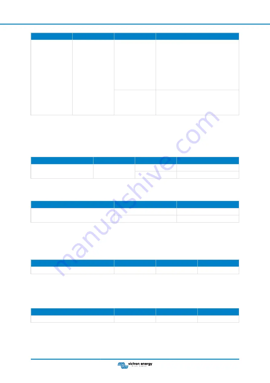
7.3.5. Relay off delay

Sets the amount of time the "de-energise relay" condition must be present before the relay opens.

An application example is to keep a generator running for a while to charge the battery better when the relay is set to "charger"
mode (

Relay mode [26]

 setting).

Setting

Default

Range

Step size

Relay off delay (setting 15)

0 minutes

0 - 500 minutes

1 minute

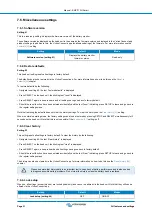
7.3.6. Low State of Charge (SoC) relay

When the state of charge percentage has fallen below the "set relay" value, the relay will close.

When the state of charge percentage has risen above the "clear relay" value, the relay will open (after a delay, depending on the

Relay minimum closed time [27]

 and/or the 

Relay off delay [27]

 settings).

Manual - BMV-710H Smart

Page 27

All features and settings

Summary of Contents for BMV-710H

Page 1: ...Manual BMV 710H Smart Battery monitor Rev 10 12 2022 This manual is also available in HTML5 ENGLISH ...

Page 2: ...he battery capacity value 13 4 4 2 Set charged voltage value 13 4 4 3 Set state of charge 13 4 5 Make Lithium settings if needed 13 5 Operation 15 5 1 How does the battery monitor work 15 5 2 Readout overview 15 5 3 Using the head unit menus 16 5 4 Trends 16 5 5 History 17 5 5 1 Accessing historical data via the VictronConnect app 17 5 5 2 Accessing historical data via the head unit 17 5 5 3 Histo...

Page 3: ...splay 30 7 5 5 Current display 30 7 5 6 Power display 30 7 5 7 Consumed Ah display 30 7 5 8 State of charge display 30 7 5 9 Time to go display 30 7 6 Miscellaneous settings 31 7 6 1 Software version 31 7 6 2 Restore defaults 31 7 6 3 Clear history 31 7 6 4 Lock setup 31 7 6 5 Shunt current 32 7 6 6 Shunt voltage 32 7 6 7 Battery starts synchronised 32 7 6 8 Bluetooth mode 32 7 7 Additional settin...

Page 4: ... charge always shows 100 40 9 3 8 State of charge does not increase fast enough or too fast when charging 40 9 3 9 Incorrect battery voltage reading 40 9 3 10 Synchronisation issues 40 10 Technical data 41 10 1 Technical data 41 11 Appendix 42 11 1 Dimensions BMV head unit 42 11 2 Dimensions BMV H shunt enclosure 42 Manual BMV 710H Smart ...

Page 5: ...ries can generate explosive gases during operation Never smoke or allow a spark or flame in the vicinity of a battery Provide sufficient ventilation around the battery Wear eye and clothing protection Avoid touching eyes while working near batteries Wash your hands when done If battery acid contacts skin or clothing wash them immediately with soap and water If acid enters an eye immediately flood ...

Page 6: ...by high ambient temperature Monitoring the battery with a battery monitor will give important feedback to the user so that remedial measures can be taken when necessary Doing this will extend battery life and the battery monitor will quickly pay for itself 2 3 Sizing The battery monitor is available in one size it has a 500A shunt However it is possible to use the battery monitor with larger shunt...

Page 7: ... Control use in case panel mounting of the battery monitor head unit is not possible Wall mount enclosure for BMV and Color Control GX use to wall mount the battery monitor head unit together with a Color Control GX in the same enclosure RJ12 UTP cable use in case the supplied 10m 32ft RJ12 cable the cable between the shunt and the head unit is too long or too short These cables are available in a...

Page 8: ...ews Spare serial number sticker 3 2 Mounting shunt enclosure The shunt enclosure has four 3 5mm holes for mounting purposes these are located in the base of the shunt enclosure The holes can be used to screw or bolt the enclosure onto a hard surface screws are not included For the exact location of the mounting holes see the dimension drawing in the appendix of this manual Manual BMV 710H Smart Pa...

Page 9: ... can be mounted in a variety of ways A Panel mounting the head unit is secured at the back of a panel B Panel mounting the head unit is secured at the front of the panel C Wall mounting using an optional wall mounting enclosure 1 2 3 Mounting method A Manual BMV 710H Smart Page 5 Installation ...

Page 10: ...hod C For the full wall mounting instructions see the wall mounting installation manuals on the Wall mount enclosure for BMV or MPPT Control or Wall mount enclosure for BMV and Color Control GX product pages Manual BMV 710H Smart Page 6 Installation ...

Page 11: ...ers connected here will be excluded from the battery state of charge calculation 3 Connect the negative of the electrical system to the M10 bolt on the LOAD side of the shunt Tighten the shunt bolt with a maximum torque of 21Nm Make sure that the negative of all DC loads inverters battery chargers solar chargers and other charge sources are connected after the shunt 4 Connect the M10 eye terminal ...

Page 12: ...an be inverted de energised becomes energised and vice versa See setting Invert relay 27 The internal wiring diagram of the battery monitor with the relay in a de energised state connected to an external alarm or generator start circuit 3 7 Use of alternative shunts The battery monitor is supplied with a 500A 50mV shunt This shunt is suitable for most applications However a larger shunt will be re...

Page 13: ...ent calibration 26 setting 3 8 GX device connection If the system contains a GX device such as a Cerbo GX the battery monitor can be connected to the GX device using a VE Direct cable or a VE Direct to USB interface Once connected the GX device can be used to read out all monitored battery parameters For more information see chapter Connecting to a GX device and the VRM portal 21 Loads Chargers Ba...

Page 14: ...ection need to be made press SELECT again and repeat the previous steps 6 Press the SETUP or button to end the setup wizard and switch to the normal operating mode Immediately after the completion of the setup wizard the battery monitor will automatically detect the nominal voltage of the battery system For details and limitations of automatic voltage detection see the next chapter The battery mon...

Page 15: ...tting item 5 Press SELECT to access the setting item 6 Use SELECT and the and buttons to customize the setting 7 Press SETUP to return to the setting menu 8 Go to the next setting using the or buttons 9 After all settings have been made press SETUP to return from the settings menu to normal mode 4 2 2 The VictronConnect app The VictronConnect app can be used to change all settings and to update th...

Page 16: ... manual only covers the items that are specific to the battery monitor For more general information about the VictronConnect app like how to use it and where to download it or how to connect see the VictronConnect app product page and manual 4 3 Update firmware On a new install it is recommended to update the firmware of the battery monitor If there is a newer firmware version available the Victro...

Page 17: ...he 12V charge voltage i e 13 2V or consult the battery documentation For more information also see the Charged voltage 24 chapter 4 4 3 Set state of charge In the VictronConnect app see Settings Battery Battery start synchronized Via the head unit see Setup menu Setting 70 Start synchronised When set to ON the battery monitor will consider itself synchronized when powered up resulting in a state o...

Page 18: ...aged due to very deep discharge or overcharge Damage due to deep discharge can occur if small loads slowly discharge the battery when the system is not in use Some examples of these loads are alarm systems standby currents of DC loads and back current drain of battery chargers or charge regulators A residual discharge current is especially dangerous if the system has been discharged all the way un...

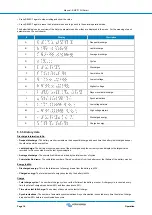
Page 19: ...n the battery monitor has just been installed or after the battery monitor has been left unpowered and is powered up again For more information see the Synchronising the battery monitor 19 chapter Voltage This is the terminal voltage of the battery Current This is the actual current flowing in or out of the battery A negative current indicates that current is taken from the battery This is the cur...

Page 20: ...xt and press again to return to normal mode When pressing SETUP while a parameter is out of range the display blinks five times and the nearest valid value is displayed SELECT Press to switch to the history menu Press to stop scrolling and show the value Press again to switch back to normal mode Press to stop scrolling after entering the setup mode with the SETUP button After editing the last digi...

Page 21: ...d or when the battery monitor has been reset to its defaults 5 5 1 Accessing historical data via the VictronConnect app The battery monitor s historical data can be accessed in the History tab in the VictronConnect app The VictronConnect app battery monitor history screen 5 5 2 Accessing historical data via the head unit To view the battery monitor history menu press SELECT when in normal mode Pre...

Page 22: ... battery monitor keeps track of the discharge during the current cycle and displays the largest value recorded for Ah consumed since the last synchronisation Average discharge The cumulative Ah drawn divided by the total number of cycles Cumulative Ah drawn The cumulative number of Amp hours drawn from the battery over the lifetime of the battery monitor Energy in kWh Discharged energy This is the...

Page 23: ...e of the VictronConnect app an alarm is acknowledged when a button is pressed And in the case of a GX device an alarm is acknowledged when viewed in notifications The alarm icon is displayed as long as the alarm condition remains Left alarm displayed on the VictronConnect app Right alarm displayed on a GX device 5 7 Synchronising the battery monitor For a reliable readout the state of charge as di...

Page 24: ...nually if required This can be done by pressing the Synchronise button in the VictronConnect app Navigate to settings and then to battery settings Alternatively the battery monitor can be synchronised when in normal operating mode by simultaneously pressing and holding the and buttons for 3 seconds A manual synchronisation can be needed in situations when the battery monitor does not synchronise a...

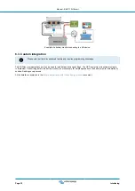
Page 25: ... USB interface connection between the battery monitor and a computer Description A VE Direct to USB interface B Computer or laptop 6 2 Connecting to a GX device and the VRM portal A GX device such as the Cerbo GX is a Victron Energy device that provides control and monitoring for all Victron equipment that is connected to it Control and monitoring of the GX device and it s connected equipment can ...

Page 26: ...port can be used to read data and change settings The VE Direct protocol is extremely simple to implement Transmitting data to the battery monitor is not necessary for simple applications the battery monitor automatically sends all readings every second All the details are explained in the Data communication with Victron Energy products document Manual BMV 710H Smart Page 22 Interfacing ...

Page 27: ...s menu click on the menu symbol For information on how to connect with the VictronConnect app to the battery monitor see the The VictronConnect app 11 chapter 7 1 3 Saving loading and sharing settings in VictronConnect In the settings menu you can find the following 3 symbols Save settings to file This will save settings for reference or for later use Load settings from file This will load earlier...

Page 28: ...voltage 24 parameter and the current has dropped below this Tail current parameter for a certain amount of time the battery monitor will set the state of charge to 100 Setting Default Range Step size Tail current setting 03 4 00 0 50 10 00 0 1 7 2 5 Charged detection time This is the time the Charged voltage 24 parameter and the Tail current 24 parameter must be met in order to consider the batter...

Page 29: ...unit this setting will be part of the miscellaneous setting and if accessed via VictronConnect it will be part of the battery settings The battery state of charge will become 100 after the battery monitor is powered up When set to ON the battery monitor will consider itself synchronised when powered up resulting in a state of charge of 100 If set to OFF the battery monitor will consider it unsynch...

Page 30: ... wires from that side of the shunt The alternative switching loads or chargers off is NOT accurate enough as this does not eliminate small standby currents Ensure that there really is no current flowing into or out of the battery disconnect the cable between the load and the shunt then press SELECT in the head unit menu or press CALIBRATE in the VictronConnect app Performing a zero current calibra...

Page 31: ...read only parameter and it displays whether the relay is open or closed de energised or energised Setting Value Description Relay state setting 13 OPEN The relay is open de energised CLSD The relay is closed energised 7 3 4 Relay minimum closed time Sets the minimum time the closed condition will remain present after the relay has been energised Note that this changes to open and de energised if t...

Page 32: ...es above the set relay value for more than 10 seconds the relay will close When the battery voltage falls below the clear relay value the relay will open after a delay depending on the Relay minimum closed time 27 and or the Relay off delay 27 settings The clear relay value needs to be greater than the set relay value Setting Default Range Step size Set relay value setting 20 0V 0 384V 0 1V Clear ...

Page 33: ...ue setting 36 1 0V 0 95 0V 0 1V Clear alarm value setting 36 0V 0 384V 0 1V 7 4 4 High voltage alarm When enabled the alarm will activate when the battery voltage rises above the set value for more than 10 seconds The alarm will deactivate when the battery voltage drops below the clear value Setting Default Range Steps Set alarm value setting 37 1 1V 0 95 0V 0 1V Set alarm value setting 37 0V 0 38...

Page 34: ...y setting 53 ON ON OFF 7 5 6 Power display Must be set to ON to display the power measurement in the monitoring menu Setting Default Modes Power display setting 54 ON ON OFF 7 5 7 Consumed Ah display Must be set to ON to display the consumed Ah in the monitoring menu Setting Default Modes Consumed Ah display setting 55 ON ON OFF 7 5 8 State of charge display Must be set to ON to display the batter...

Page 35: ...r the history settings To clear the history see the Clear history 31 setting When in normal operating mode the factory settings can also be restored by pressing SETUP and SELECT simultaneously for 3 seconds on the head unit Note that this is only possible if the Lock setup 31 setting is off 7 6 3 Clear history Setting 63 This setting resets all settings to factory default To clear the history do t...

Page 36: ...onnect settings menu but are located elsewhere in the VictronConnect app 7 7 1 Reset history This setting can be found at the bottom of the history tab This setting can also be made via the head unit For more information see the Clear history 31 chapter Please be aware that history data is an important tool to keep track of battery performance and is also needed to diagnose possible battery proble...

Page 37: ...y Monitor B and so on 7 7 7 Firmware Both the battery monitor and its Bluetooth interface run on firmware Occasionally a newer firmware version is available New firmware is released to either add features or to fix a bug The product overview in the VictronConnect app displays the battery monitor and the Bluetooth interface firmware version It also indicates whether the firmware is the latest versi...

Page 38: ...This setting is also available via the head unit For more information see the Restore defaults 31 chapter Manual BMV 710H Smart Page 34 All features and settings ...
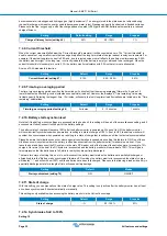
Page 39: ...ttery monitor takes this phenomenon into account with Peukert exponent Discharge rate example A lead acid battery is rated at 100Ah at C20 this means that this battery can deliver a total current of 100A over 20 hours at a rate of 5A per hour C20 100Ah 5 x 20 100 When the same 100Ah battery is discharged completely in two hours its capacity is greatly reduced Because of the higher rate of discharg...

Page 40: ...tp www victronenergy com support and downloads software peukert calculator Please note that the Peukert exponent is no more than a rough approximation of reality In case of very high currents the battery will give even less capacity than predicted by a fixed exponent We do not recommend changing the default value in the battery monitor except in the case of lithium batteries Manual BMV 710H Smart ...

Page 41: ...you close enough to the battery monitor In an open space the maximum distance is about 20 meters Are you using the Windows version of the VictronConnect app This version is unable to connect via Bluetooth Use Android iOS or macOS instead or use the USB VE Direct interface For connection issues see the troubleshooting section of the VictronConnect manual https www victronenergy com live victronconn...

Page 42: ...not flow through the battery monitor and will be excluded from the overall current reading and the state of charge reading The battery monitor will display a higher state of charge than the actual state of charge of the battery 9 3 3 There is a current reading while no current flows If there is a current reading while no current is flowing through the battery monitor perform a zero current calibra...

Page 43: ...detection time Not occasionally fully charging the battery For more information on these parameters see the chapter Battery settings Incorrect state of charge due to incorrect current reading The state of charge is calculated by looking at how much current flows in and out of the battery If the current reading is incorrect the state of charge will also be incorrect See paragraph Incomplete current...
Page 44: ...not midway of the battery bank 9 3 10 Synchronisation issues If the battery monitor does not synchronise automatically one possibility could be that the battery never reaches a fully charged state Fully charge the battery and see if the state of charge eventually indicates 100 Another possibility is that the charged voltage setting 24 should be lowered and or the tail current setting 24 should be ...

Page 45: ...surement 0 4 Accuracy of voltage measurement 0 3 INSTALLATION DIMENSIONS Installation Flush mount Head unit front diameter 63mm 2 5 inch Head unit front bezel 69 x 69mm 2 7 x 2 7 inch Shunt connection bolts M10 0 3937 inch Head unit body diameter and depth 52mm 2 0 inch and 31mm 1 2 inch Head unit protection category IP55 not intended for outdoor use STANDARDS Safety EN 60335 1 Emission Immunity E...

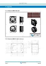
Page 46: ...tor BMV 702 Retail BAM010702200 Battery Monitor BMV 702 BLACK BAM010702200R Battery Monitor BMV 702 BLACK Retail BAM030712000 Battery Monitor BMV 712 Smart BAM030712000R Battery Monitor BMV 712 Smart Retail BAM030712200 Battery Monitor BMV 712 BLACK Smart BAM030712200R Battery Monitor BMV 712 BLACK Smart Retail Dimensions in mm D E F C 1 2 3 4 B A 3 2 1 5 C D 4 6 7 8 A B 8 7 6 5 F E 11 2 Dimension...

Reviews: