background image

Installation & set-up guide

Summary of Contents for BSLBATT

Page 1: ...Installation set up guide ...

Page 2: ...s of the BSL battery should always be considered live therefore do not place tools or any other items across the terminals Do not pierce short or damage the terminals in any way Do not touch the terminals of the battery Fire Hazard Do not discharge battery below specified minimum level as this poses an increased fire risk Do not attempt to charge a swollen or damaged battery In the event of fire a...

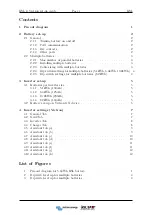
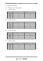
Page 3: ...s for multiple batteries 8 2kWh 4 3 Inverter set up 5 3 1 Batteries per inverter size 5 3 1 1 5 1kWh 100Ah 5 3 1 2 6 4kWh 125Ah 5 3 1 3 10 2kWh 200Ah 5 3 1 4 8 2kWh 160Ah 5 3 2 Battery set up on Victron GX device 6 4 Inverter settings Victron 7 4 1 General Tab 7 4 2 Grid Tab 7 4 3 Inverter Tab 8 4 4 Charger Tab 8 4 5 Assistant tab a 9 4 6 Assistant tab b 9 4 7 Assistant tab c 10 4 8 Assistant tab ...

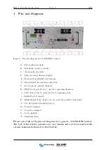
Page 4: ...ntacts mostly unused H RS485 Left port Port 1 used for updating firmware I CAN Port Port 2 used for CAN communication J RS232 Port Unused K RS485 Right Ports Ports 4 5 used for parallel connections L Circuit breaker terminal power M Positive terminal N Negative terminal O Carry handles P Mounting holes Please note this is the pin out diagram for a generic 5 1kWh BSL battery The rest of the battery...

Page 5: ...e check this with inverter suppliers Black to in verter GX device red to battery A Battery Monitoring Device Victron BMV Smartshunt is not required as State of Charge SOC is sent to the GX device via the CAN Bus cable 2 1 3 Dry contacts Dry Contacts are mostly unused but for communication with some non smart systems please see the table below Working current should be less than 2A mainly to connec...

Page 6: ...ng between the battery and bus bar must be the same length and all negative cables must be the same length The batteries should be evenly grouped where possible 5 1kWh 100Ah The recommended battery cable sizes from the batteries going to the inverter in par allel are as follows 1 battery 35mm2 2 batteries 50mm2 3 batteries 70mm2 or 2 35mm2 4 batteries 95mm2 or 2 50mm2 6 4kWh 125Ah The recommended ...

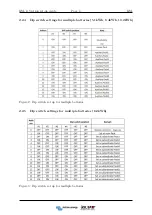
Page 7: ...4 BSL 2 2 4 Dip switch settings for multiple batteries 5 1kWh 6 4kWh 10 2kWh Figure 2 Dip switch set up for multiple batteries 2 2 5 Dip switch settings for multiple batteries 8 2kWh Figure 3 Dip switch set up for multiple batteries ...

Page 8: ...2 1 3kVA 1 1 3 1 2 6 4kWh 125Ah Inverter size Recommended N O batteries Minimum N O of batteries 15kVA 4 3 10kVA 3 2 8kVA 2 2 5kVA 2 1 3kVA 1 1 3 1 3 10 2kWh 200Ah Inverter size Recommended N O batteries Minimum N O of batteries 15kVA 4 3 10kVA 3 2 8kVA 2 2 5kVA 1 1 3kVA 1 1 3 1 4 8 2kWh 160Ah Inverter size Recommended N O batteries Minimum N O of batteries 15kVA 3 2 10kVA 2 2 8kVA 2 1 5kVA 1 1 3k...

Page 9: ...e Scroll down to settings press enter and scroll to services and press enter again Navigate to the CAN settings and change the CAN speed from 250 KB to 500 KB 3 Scroll to DVCC and select Switch DVCC on Flag SHARED VOLTAGE SENSE and CHARGE LIMIT un flag SWITCH OFF Set CCL charge current limit to 50 amps battery 4 Navigate back to the device list and the BSL battery should appear on the device list ...

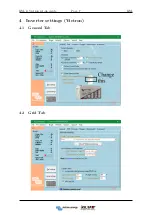
Page 10: ...BSL Victron set up guide Page 7 BSL 4 Inverter settings Victron 4 1 General Tab 4 2 Grid Tab ...

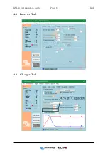
Page 11: ...BSL Victron set up guide Page 8 BSL 4 3 Inverter Tab 4 4 Charger Tab ...

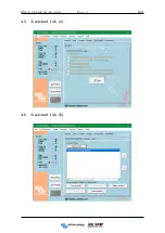
Page 12: ...BSL Victron set up guide Page 9 BSL 4 5 Assistant tab a 4 6 Assistant tab b ...

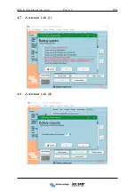
Page 13: ...BSL Victron set up guide Page 10 BSL 4 7 Assistant tab c 4 8 Assistant tab d ...

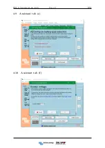
Page 14: ...BSL Victron set up guide Page 11 BSL 4 9 Assistant tab e 4 10 Assistant tab f ...

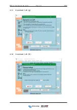
Page 15: ...BSL Victron set up guide Page 12 BSL 4 11 Assistant tab g 4 12 Assistant tab h ...

Reviews: