BSL & Victron set-up guide
Page 2
BSL
2
Battery set-up
2.1
General
2.1.1
Turning battery on and off
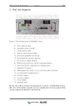
The battery can be switched on or off by holding down the small recessed button marked
“RESET” for around 3 seconds.
2.1.2
CAN communication
To connect a VE.Can or CAN-bus BMS “Type B” cable is required for CAN-Bus com-
munication between the BSL battery and the Victron GX device. Some inverters will
use different cable configuration, please check this with inverter suppliers.(Black to in-
verter/GX device, red to battery).
A Battery Monitoring Device (Victron BMV/Smartshunt) is not required as State of
Charge (SOC) is sent to the GX device via the CAN-Bus cable.
2.1.3
Dry contacts
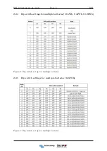
Dry Contacts are mostly unused, but for communication with some non-smart systems
please see the table below. Working current should be less than 2A, mainly to connect
with an external indicator light or buzzer. The low battery signal should be at 10% of
the battery capacity.
2.1.4
Other ports
Port 1 (RS485) and port 3 (RS232) are used for programming and retrieving information
only and must be left open.
Summary of Contents for BSLBATT
Page 1: ...Installation set up guide ...
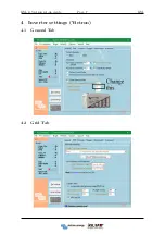
Page 10: ...BSL Victron set up guide Page 7 BSL 4 Inverter settings Victron 4 1 General Tab 4 2 Grid Tab ...
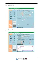
Page 11: ...BSL Victron set up guide Page 8 BSL 4 3 Inverter Tab 4 4 Charger Tab ...
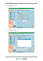
Page 12: ...BSL Victron set up guide Page 9 BSL 4 5 Assistant tab a 4 6 Assistant tab b ...
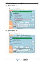
Page 13: ...BSL Victron set up guide Page 10 BSL 4 7 Assistant tab c 4 8 Assistant tab d ...
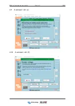
Page 14: ...BSL Victron set up guide Page 11 BSL 4 9 Assistant tab e 4 10 Assistant tab f ...
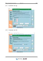
Page 15: ...BSL Victron set up guide Page 12 BSL 4 11 Assistant tab g 4 12 Assistant tab h ...

