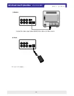
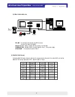
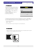
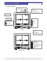
background image

19

4Ch Real time/Triplex/Mux

- Stand Alone DVR

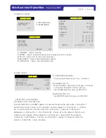
5-2. DISPLAY SETUP

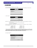
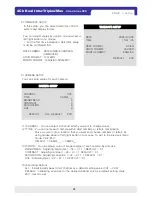
1) VGA SETUP

This is setup menu for display on the screen.
If you click ‘DISPLAY SET UP’, then you change setting values for display as shown below.

VGA SETUP : Connection to a VGA monitor (CRT/TFT LCD), if optional VGA board is fixed on 

the main board.
You can set ‘RESOLUTION’ for VGA as shown below.
(VGA Default is 800X600.)

*If there is no VGA option board fixed on the main board or not detected correctly, it displays 
“No VGA BOARD”

640X480 / 60Hz
800X600 / 60Hz

1024X768 / 60Hz

1280X1224 / 60Hz

640X480 / 75Hz
800X600 / 75Hz

1024X768 / 75Hz

1280X1024 / 75Hz

CHAP.  5  Set up

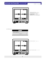
VGA SETUP
SCREEN DISPLAY
OSD SETUP

ESC

DISPLAY SETUP

RESOLUTION                           800 X 600 / 75Hz

DEFAULT    ESC

VGA SETUP

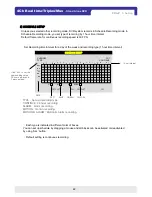
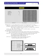
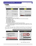
2) SCREEN DISPLAY

VERTICAL POSITION                                        24
HORIZONTAL POSITION                                   00
BOARDER ENABLE                                         ON       
BOARDER WIDTH                                            01    
BOARDER COLOR                                       GRAY

DEFAULT           ESC

SCREEN DISPLAY

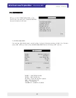
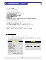
** Please check the resolution range that your VGA monitor supports first before you use VGA monitor.  
If you select high resolution such as 1024X768, 1280X1224 on VGA SETUP with VGA monitor that does 
NOT support those high resolutions, image display may NOT be seen properly.

Summary of Contents for VSD-31

Page 1: ...The most stable and reliable real stand alone Digital Video Multiplex Recorder Stand Alone DVR 4Ch Real time Triplex Mux VER 1 2 User s Manual 4 Channel Stand Alone DVR USB Backup available VSD 31...

Page 2: ...other hazards 3 Installation should be performed by qualified service personnel only 4 This unit should be operated only from the type of power source indicated on the manufacturer s label and with th...

Page 3: ...2 12 System Log In 4 1 14 PIP View 3 14 SEQ 2 14 Full Multiple View 1 14 Live View Setup 4 4 17 Data Back up 4 9 12 Operation CHAP 4 11 RS 232 ASCII Code 6 10 Power 4 10 Monitor 3 9 Camera 2 9 HDD Har...

Page 4: ...for DDNS 7 1 42 Web Viewer Setup CHAP 7 54 Specifications CHAP 8 28 Pan Tilt Zoom Setup 2 26 Alarm Setup 6 26 Password Setup 7 25 Motion Setup 4 26 Interval Setup 5 24 Camera Setup 3 24 Time Date Setu...

Page 5: ...hedule recording Event Record by alarm and motion detection Network Monitoring and Search by using Remote Viewer via network Playback Search and playback by recorded data size and date time Various st...

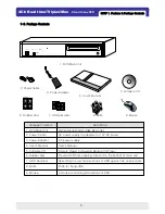
Page 6: ...ts Absorbing the mechanical shock of HDD against the case bottom 7 HDD absorber Prevent DVR from slipping Attach it to the bottom of main unit 6 Rubber Pad Remote Viewer Software Backup CD Player 5 So...

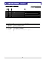
Page 7: ...status of operation LED Lamps Used for Data Backup and Firmware upgrade CD RW Used for Data Backup USB HOST Used for updating Firmware USB Device Function Name CHAP 2 Function of Each Button 2 1 Front...

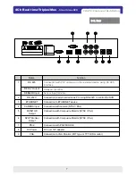
Page 8: ...mera or other external device using RS 485 interface RS 485 VGA SPOT Monitor Output Connection to VGA Monitor CRT type or TFT LCD monitor Connection with Composite Monitor NTSC PAL Connection with Com...

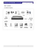
Page 9: ...8 4Ch Real time Triplex Mux Stand Alone DVR 3 1 Installation Configuration CHAP 3 Installation CHAP 3 Installation...

Page 10: ...ting of HDD should be on Master when you install HDD 3 Stick the HDD absorber included in package on the bottom of case and then install the HDD on top of them by using the bolts included in package 4...

Page 11: ...10 4Ch Real time Triplex Mux Stand Alone DVR 4 Power DC over 12V adapter CHAP 3 Installation 3 Monitor Connect the video output marked MONITOR to Video In of Main monitor...

Page 12: ...nsor Input Alarm Input Pin No 1 No 4 at D SUB ETHERNET Connection to LAN WAN t CHAP 3 Installation 6 RS 232C ASCII code Following ASCII Codes Hexa Code are for programmers who want to control DVR unit...

Page 13: ...ee DVR Log In message shown as right 3 You may log in as a ADMIN MANAGER or USER1 USER8 4 Input your password Max 8 digits are available for password 5 To exit click EXIT button If the password entere...

Page 14: ...ard Playback speed up Playback speed down SEARCH STOP Current Date Time ETHERNET Status connected Disconnected Remote Search Alarm Record Motion Record Continuous Record Live Display Playback Display...

Page 15: ...con It automatically displays full screen images in sequence You can setup SEQ time interval on setup menu SCREEN SETUP SEQEUNCE INTERVAL When it is in full screen display mode you can see other camer...

Page 16: ...a firmware When you are in HDD management menu mode 1 On record mode or stop mode click click to play the recorded data in 1x speed 2 How to use a mouse Left button on a mouse is used for all command...

Page 17: ...TIME CHANNEL EVENT PAGE 000 000 ESC EVENT SEARCH There are three search methods controlled by a mouse wheel button left and right button of a mouse When you click SEARCH icon then you see a window sho...

Page 18: ...ize of back up data from start of back up but END of back up time is automatically determined by DVR itself 3 Click BURN then it starts burning a CD 4 When burning is completed CD R media will come ou...

Page 19: ...ENGLISH EXIT MAIN MENU MAIN MENU Increase of setup value on the Menu mode Execute all of the function clicking icons Decrease of setup value on the Menu mode Up and down of setup value on the Menu mod...

Page 20: ...displays No VGA BOARD 640X480 60Hz 800X600 60Hz 1024X768 60Hz 1280X1224 60Hz 640X480 75Hz 800X600 75Hz 1024X768 75Hz 1280X1024 75Hz CHAP 5 Set up VGA SETUP SCREEN DISPLAY OSD SETUP ESC DISPLAY SETUP...

Page 21: ...R 3 OSD SETUP CHAP 5 set up TOP OSD OFFSET 0 BOTTOM OSD OFFSET 0 DEFAULT ESC OSD SETUP TOP OSD OFFSET 10 9 BORDER ENABLE ON OFF BORDER WIDTH 1 10 BORDER COLOR COLOR SELECT VERTICAL POSITION 0 63 HORIZ...

Page 22: ...ange setup value by using a mouse 1 CHANNEL CHANNEL select 2 QUALITY Set recording picture quality There are five quality steps LOWEST LOW NORMAL DEFAULT HIGH HIGHEST To send more images via IP networ...

Page 23: ...records in Schedule Recording mode In Schedule Recording mode you set type of recording by 1 hour time interval Default frame rate for continuous recording speed is 30 FPS Set Recording time interval...

Page 24: ...LOCK Number SIZE HDD TOTAL SIZE SPEED HDD MODE OVERWRITE ENABLE DISABLE CHAP 5 Set up HDD MANAGEMENT CAMERA SETUP MOTION SETUP ALARM SETUP INTERVAL SETUP TIME DATE SETUP PASSWORD SETUP ESC CONFIGURATI...

Page 25: ...ous menu mode click ESC DEFAULT CAM01___ CAM03___ 3 COLOR You can adjust color of image display of each camera by a mouse BRIGHTNESS Adjusting brightness 32 31 DEFAULT 0 CONTRAST Adjusting contrast 32...

Page 26: ...e to the location which you don t want to detect and then click it by using left button Motion is detected when the cell is activated Motion is not detected on non activated cells BLOCK ON Select non...

Page 27: ...HANNEL INPUT DURATION ALL DEFAULT ALRAM SETUP INPUT Select NORMAL OPEN NORMAL CLOSE or DISABLE DISABLE represents not to use alarm sensor connected to DVR DURATION Set the duration of alarm when an AL...

Page 28: ...rk information assigned to the DVR unit If the DHCP setup status is AUTOMATIC you can set the IP port only and if the DHCP setup status is MANUAL you must set all parameters If IP port number is block...

Page 29: ...ON MOTION POP UP ON EVENT POP UP DURATION 05 SEC DEFAULT ESC SPOT SETUP 1 SWITCHING INTERVAL Channel switching time 01 sec 99 sec 2 ALARM POP UP When ALARM is detected the image of channel connected w...

Page 30: ...3 SIZE 700 MB 700MB BURN ESC You can back up the recorded data to CD using CD writer installed in DVR Refer to START and END of data on HDD and set copy from time START and size of data copied SIZE an...

Page 31: ...stem USER ID ADMIN USER PW ________ ENTER EXIT DVR LOG IN System Status Messages 1 If MEMORY STICK is not inserted USB STORAGE IS CHECKING USB STORAGE IS NOT AVAILABLE RE CONNECT THE USB STORAGE CONEC...

Reviews: