background image


Receiver Setup  


For the wireless link to work, both devices must have the same channel selected. 


1.


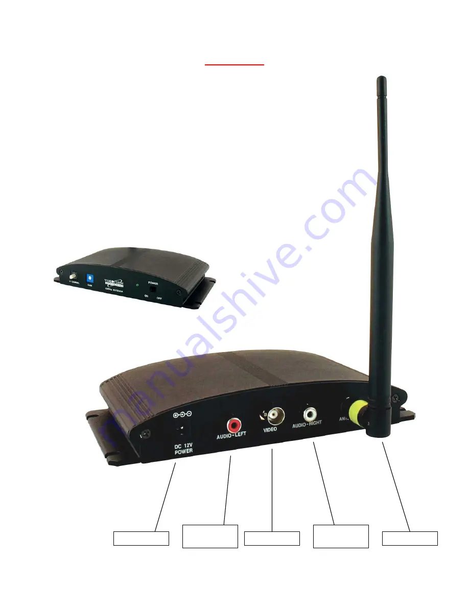
Attach the included rubber duck antenna to the SMA connector on receiver. 

2.


Power-UP the Receiver using the included power supply & switch to “ON” 

3.


Set the desired channel by turning the rotary switch to channels from 1 – 8 

4.


The receiver must be set to the same channel as the camera. 

5.


Connect video cable from receiver output connector to monitor source 

6.


We strongly recommend that you do not adjust the video gain adjustment without  
first consulting a member of the VideoComm Technologies Tech Support Team. 


BNC-Female

RCA-Female

Not-Used

2.1mm Barrel 

SMA-Female

RCA-Female 

Not-Used 

Summary of Contents for EWC-002

Page 1: ...1 EWC 001 002 5 8GHz Wireless Camera Series It s About Real Time OWNER S MANUAL ...

Page 2: ...llation of all antennas must be performed in a manner that will provide at least 23cm clearance from the front radiating aperture to any user or member of the public III This is NOT an intrinsically safe device Do not take into area where intrinsic safety is required Bodily harm may result if warning is ignored IV DO NOT OPERATE WIRELESS CAMERA WITHOUT ANTENNA CONNECTED TO ANTENNA PORT Failure to ...

Page 3: ...ance and monitoring applications Perfect for any indoor camera application including office warehouse retail stores or nursery Advantages Easy to install and operate with all accessories included 8 user selectable channels NO interference from 2 4GHz 802 11 b g data devices 5 8GHz low profile desktop receiver included with some models High resolution CCD camera Low current consumption for convenie...

Page 4: ...ck into the bottom of camera RED LED light will confirm power 4 NOTE The wireless camera does not have an ON OFF switch and therefore the moment you connect a power source to the wireless camera it is operational Important if using a battery supply 5 See specifications for operating voltage range Higher than 13VDC can permanently damage the wireless camera Lower than 8VDC of operating voltage the ...

Page 5: ...occur 4 Repeat these steps for the receiver The receiver must have the same and matching channel as the wireless camera to receive the video signal 5 Do Not bend the black part of the antenna Channel 1 5 733 GHz Channel 6 5 828 GHz Channel 2 5 752 GHz Channel 7 5 847 GHz Channel 3 5 771 GHz Channel 8 5 866 GHz Channel 4 5 790 GHz Channel 9 5 866 GHz Channel 5 5 809 GHz Channel 0 5 733 GHz Receiver...

Page 6: ...N 3 Set the desired channel by turning the rotary switch to channels from 1 8 4 The receiver must be set to the same channel as the camera 5 Connect video cable from receiver output connector to monitor source 6 We strongly recommend that you do not adjust the video gain adjustment without first consulting a member of the VideoComm Technologies Tech Support Team BNC Female RCA Female Not Used 2 1m...

Page 7: ...e recommend using wall plugs to support the weight of the camera Not Included 2 Insert camera between U type bracket and secure with mini screws included 3 Pivot camera up down as required to achieve desired video picture angle Tighten mini screws for permanent mount 4 Plug in power supply source and re confirm successful video picture Add optional high gain receiver antenna to improve distance or...

Page 8: ...mmend using wall plugs to support the weight of the camera Not Included 2 Insert camera between U type bracket and secure with mini screws included 3 Pivot camera up down as required to achieve desired video picture angle Tighten mini screws for permanent mount 4 Plug in power supply source and re confirm successful video picture Add optional high gain receiver antenna to improve distance or elimi...

Page 9: ... siding and energy saving foil on the insulation in the walls are sneaky killers for radio waves Some metallic paints or metallic wallpapers also block signals Mirrors block transmission because the mirror consists of a metallic backing on the glass Lead windows will kill radio transmission also windows that are UV coated may have thin metal energy saving film Other materials like brick drywall or...

Page 10: ...Antenna Type 0dB Fixed OmniDirectional Receiver Antenna Type 3dB Removable OmniDirectional Receiver Sensitivity 84 dBm Video Format NTSC and PAL Modulation FM Frequency Modulation Video Output BNC Female 75 Ohms 1 Volt P P Temperature Range 22 to 140 degrees Fahrenheit Operating Voltage 9 14 VDC Polarity Protected Current Consumption Camera 150mA 12VDC Receiver 170mA 12VDC Dimensions Receiver 7 4 ...

Reviews: