Programming/RF Testing/Mounting
The following provides summarized steps for device
programming, testing and mounting. For complete details, refer to
the control panel installation manual.
1
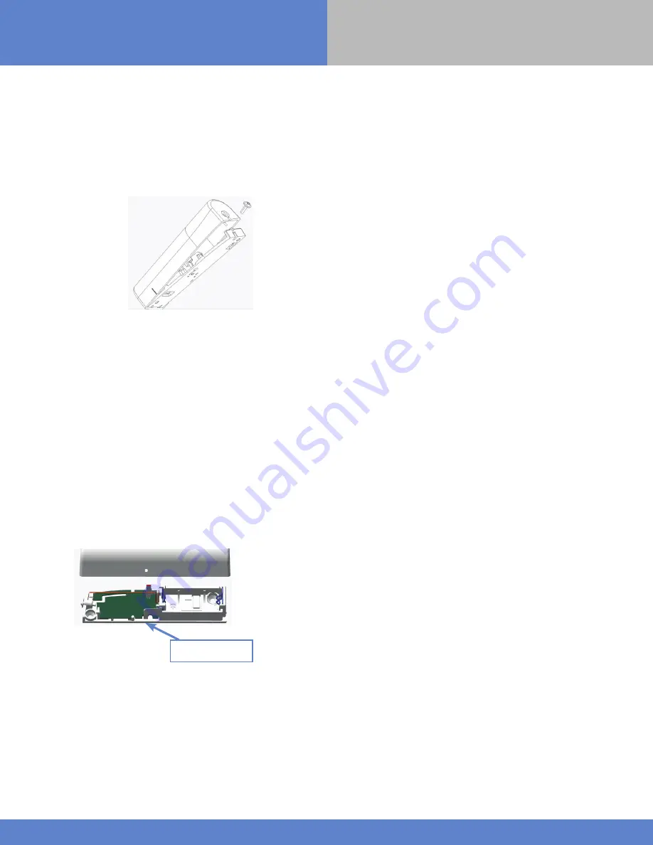
Loosen bottom screw and separate base from detector.
2
Install 1 Duracell CR123 3v Lithium battery, observing correct
polarity.
*Check that the LED flashes before staying RED
3
Put control panel into programming/configuration mode.
4
Using a programmed alphanumeric keypad, proceed through
menus until the display shows ADD A NEW DEVICE.
5
Press YES/OK. The display shows PRESS PROGRAM BUTTON OF
DEVICE.
6
Press and release program button on detector. The detector
LED flashes. Wait for keypad display to show DETECTOR (1 - 25)
RECORDED.
7
Press YES/OK. The display shows RADIO RANGE TEST?
Press YES/OK again. The detector LED starts flashing and
keypad display shows TEST IN PROGRESS.
8
Take detector to its intended mounting location and make sure
LED flashes continuously, indicating good communication with
control panel.
9
Press YES/OK to end radio range test, then press Esc/ No.
10
The display shows AREA ASSIGNMENT AREA: 1. Press either
arrow button repeatedly until desired AREA number appears, then
press YES/OK.
11
The display shows PERIMETER DEVICE?
Press YES/OK or Esc/No, whichever is appropriate for this device.
12
The display shows NAME + LOCATION:
Enter appropriate device name/location (up to 16 characters), then
press YES/OK. The display shows the device number and name for
your verification.
13
Press YES/OK. The display shows FUNCTIONAL DEVICE
TEST? Press YES/OK again and verify detector operation. For
example, move magnet next to detector to make LED go out, then
move magnet away from detector to make LED turn on indicating
detection.
14
Press YES/OK to end detection verification.
15
The display shows ENTERING A NEW DEVICE?
Repeat steps 1 - 14 for remaining detectors.
16
When finished, exit from configuration mode.
Note: Only contacts protecting the external access should be
configured for Perimeter arming.
Programming
Button
www.videofied.com
P R O D U C T I N S T A L L A T I O N
S H E E T
2
Indoor Door Contact
IDC200/601/701


