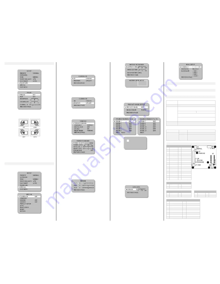
IMAGE ADJUSTMENT
When the SETUP menu screen is displayed, select 'IMAGE
ADJ.' using the Up and Down buttons.
•
FREEZE: View still pictures.
o
OFF / ON selectable
•
FLIP: OFF / HORIZ / VERT / BOTH selectable
•
SHARPNESS: The outline of the video image becomes
cleaner and more distinctive as the level of
SHARPNESS increases. If the level goes up
excessively, however, it may affect the video image
and generate noise.
o
The available range of level is -8 ~ 8
•
COLOR GAIN: To control the color level in the video.
o
The available range of level is -8 ~ 8
•
GAMMA : Users can change the gamma setting
between 25 and100
SPECIAL
When the SETUP menu screen is displayed, select
'SPECIAL' by using the Up and Down buttons so that the
arrow indicates 'SPECIAL'.
•
CAMERA ID: User can enter a unique name for the
respective camera. The maximum length of the ID is
ten characters.
o
You can choose the ON and OFF with the selector.
If you select ON, the entered camera ID is
displayed at the selected position in the video
picture (normal operation).
o
Please select the setup button while in ON mode.
o
Select the desired position with the selector.
1.
Move the cursor to the letter required by using the
Set-Up button.
2.
Select an ID from A, B~Y, Z, a, b~y, z, 0, 1~8, 9 by
using the LEFT and RIGHT buttons.
3.
Repeat the above steps until the ID is complete.
1.
Select the position where the ID is to be displayed by
using the LEFT and RIGHT buttons.
•
VIDEO I/O: Move the cursor to select the video
system.
o
VIDEO STANDARD: You can control NTSC / PAL,
Video level, Sync level, Burst level.
o
VIDEO OUT: Interlace/ Progressive Video
selectable.
o
DIGITAL OUT: Digital output ON/OFF selectable.
o
656 OSD: Digital output OSD ON/OFF selectable.
o
FIELD ORDER: Normal/Reverse Field selectable.
•
DZOOM: Digital P/T/Z is used to create a zoom lens
effect.
Zoom Factor (1X to 4X), Pan (±100%, center of image
can be moved to left and right edges of screen), Tilt
(±100%, center of image can be moved to top and
bottom edges of screen)
● MOTION: This product has a feature that allows you to
observe movements of objects on the screen; hence a
single individual can conduct supervision efficiently. The
camera detects an object's movement by sensing
disparity of outline, and level of brightness and color.
o
White: MOTION ZONE Position movement
Green: MOTION ZONE Size enlargement
Red: MOTION ZONE Size reduction
o
For MOTION ZONE Confirm, long press SET button
•
PRIVACY SETUP: Hide an area you want to hide on
the screen.
o
White: PRIVACY-ZONE Position movement.
o
Blue: PRIVACY-ZONE Size enlargement or
reduction.
o
For PRIVACY-ZONE Confirm, long press SET button.
•
SYNC: Two synchronization modes are available,
INTERNAL and EXTERNAL LINELOCK. In LINE-LOCK
mode, it synchronizes the video signal between
cameras without a synchronous generator. The line-
lock synchronization is only used in areas of 60Hz
(NTSC)/ 50Hz (PAL).
o
INT: Internal synchronization
o
LL: External line-lock synchronization
If 'LL' is selected, it can be adjusted to the desired
phase.
Press the SET button.
o
Adjust to the desired phase from 0 to 360.
•
RS485 SETUP: This function sets up the camera
communication status when controlling the camera
through an external control device.
RESET
Resets the camera settings to the factory defaults.
EXIT MENU
Saves all the setting menus and then exits.
SPECIFICATIONS
MECHANICAL
Dimensions
WxHxD
42mm x 42mm x 18.2mm
(1.65” x 1.65” x 0.71”)
Weight
43g (1.51oz)
Lens Mounts Replace “X” in model number with desired
lens mount option:
5=Metal M-12 Board 6 = Metal M-14 Board
Example: Change 20C40XW to 20C405W to
select an M-12 Board Mount.
Change 20C40XW to 20C406W to select an
M-14 Board Mount.
Lens
See our lenses at:
www.videologyinc.com/lenses
ACCESSORIES
Included
BNC/power cable
Optional
60ZRC10
OSD control board
60C1001
30 pin - 20 pin digital output
cable (digital camera only
20/21C40XWD)
PIN ASSIGNMENT
J6 (30 PIN) Digital Signal
1
16 GND
2
17 DV3
3
18 DV9
4
19 DV4
5
20 DV8
6
21 DV5
7
22 DV7
8 RXDV
23 GND
9 DV0
24 DV6
10 TXDV
25 RESET
11 DV1
26 GND
12 GND
27
13 DV2
28
14 DVCLK
29
15 GND
30
J2 (4 PIN) IRIS
1 DMP+
3 DRV+
2 DMP-
4 DRV-
J8 (4 PIN) PELCO-D
J9 (4 PIN) I/O
1 VCC3V3 3 TX
1 UTP+
3 GPIO00
2 RX
4 GND
2 UTP-
4 GPIO01
J3 (15 PIN)
MAIN CONNECTOR
1 VIDEO
8 KEY_DOWN
2 VIDEO_GND 9 KEY_UP
3 DC12V
10 KEY_SET
4 GND
11 KEY_RIGHT
5 LINE-LOCK
12 KEY_LEFT
6 GND
13 M/D_OUT
7 EXTRA_VIDEO 14 IRIS SIGNAL
15 D/N_SEL


