


Annex I - Installation report
108
80028124_030_A – 773701 – 2021-04-29
VDM 8602
pag. 3/6
23/03/2020
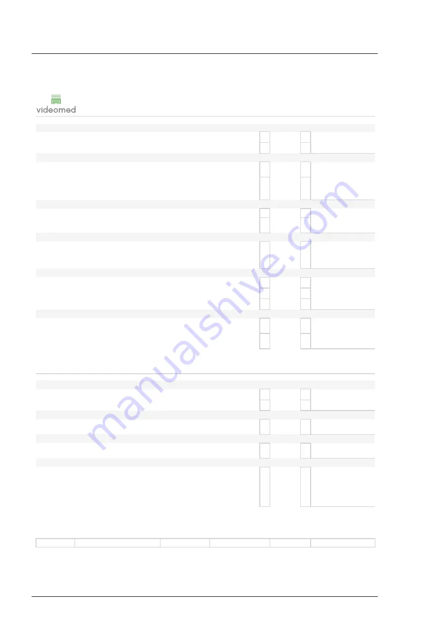
1. Verify parts integrity, cleaning status and closure systems.
2. Verify presence of labels for rear connections, S/N and identification.
POWER
1. Connect the power cord, verify the automatic switching ON and OFF of the unit following Main
Unit status.
INTERNAL AND EXTERNAL CONNECTIONS
1. Check the cabling between Conference and Main Units.
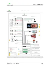
2. Check the connections of the signals coming from the OR by referring to the Cabling Plan
provided by Videomed.
OK Failed Notes
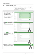
ROOMCAM
1. Verify proper configuration of the roomcam (ceiling or std mounting).
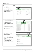
ROUTING IMAGES
1. Switch on the system and send the Videoconference signal to a monitor via Routing function.
Open the Conference section and select an image on the first channel. Verfiy that the right signal is
displayed on monitor. Verify that channel 1 and 2 are properly connected and identified.
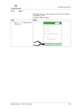
NETWORK CONNECTIONS
1. If provided, set the static IP on network settings and check the connections with the local network
and the other units of the system.
2. Move the camera in all directions until the mechanical limit.
3. Memorize 3 preset positions and recall them.
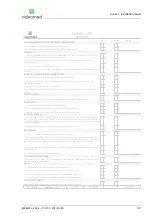
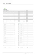
CHECK-LIST
UHD Unit
MECHANICAL STATUS AND INTERNAL COMPONENTS
1. Verify parts integrity, cleaning status and closure systems.
2. Verify presence of labels for rear connections, S/N and identification.
1. Check the cabling between Main and UHD unit, following the "internal cabling plan".
Installation report
rev. 00
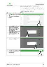
ROUTING AND DOWNSCALE
1. Connect an UHD source, with 4096x2160 p50/60 resolution, to each one of the configureed
inputs. Check if the preview and live preview are properly displayed on touchscreen. Send the
signal to each one of the monitors (4K and FHD) installed and check if a stable image is displayed
for at least 2 minutes. Try to intersperse FHD and 4K images on 4K monitors and check if monitor
can properly hand the switch.
1. On Configurator set the IP and check the communication between Main and Conference units.
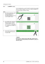
POWER
INTERNAL AND EXTERNAL CONNECTIONS
1. Connect the power supply and switch ON the unit. Turn on Truelink 4 and verify the automatic
start.
2. Execute a forced shut switching off the main power button, and switch it on again after few
seconds to simulate a power black out. Check the regular re-start of all the components and
functions.
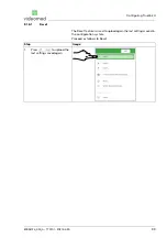
CHECK-LIST
CONFERENCE Unit
OK Failed Notes
MECHANICAL STATUS AND INTERNAL COMPONENTS
Summary of Contents for TAC500920K
Page 1: ...Service Manual Truelink 4 Video Management System ENGLISH en US...
Page 2: ...This page is intentionally blank...
Page 6: ...Truelink 4 6 80028124_030_A 773701 2021 04 29 This page is intentionally blank...
Page 113: ...This page is intentionally blank...
Page 114: ...80028124_030_A 773701 2021 04 29...


