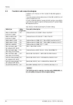


Components installation
44
80028124_030_A – 773701 – 2021-04-29
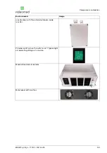
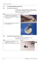
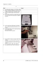
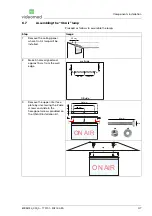
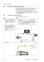
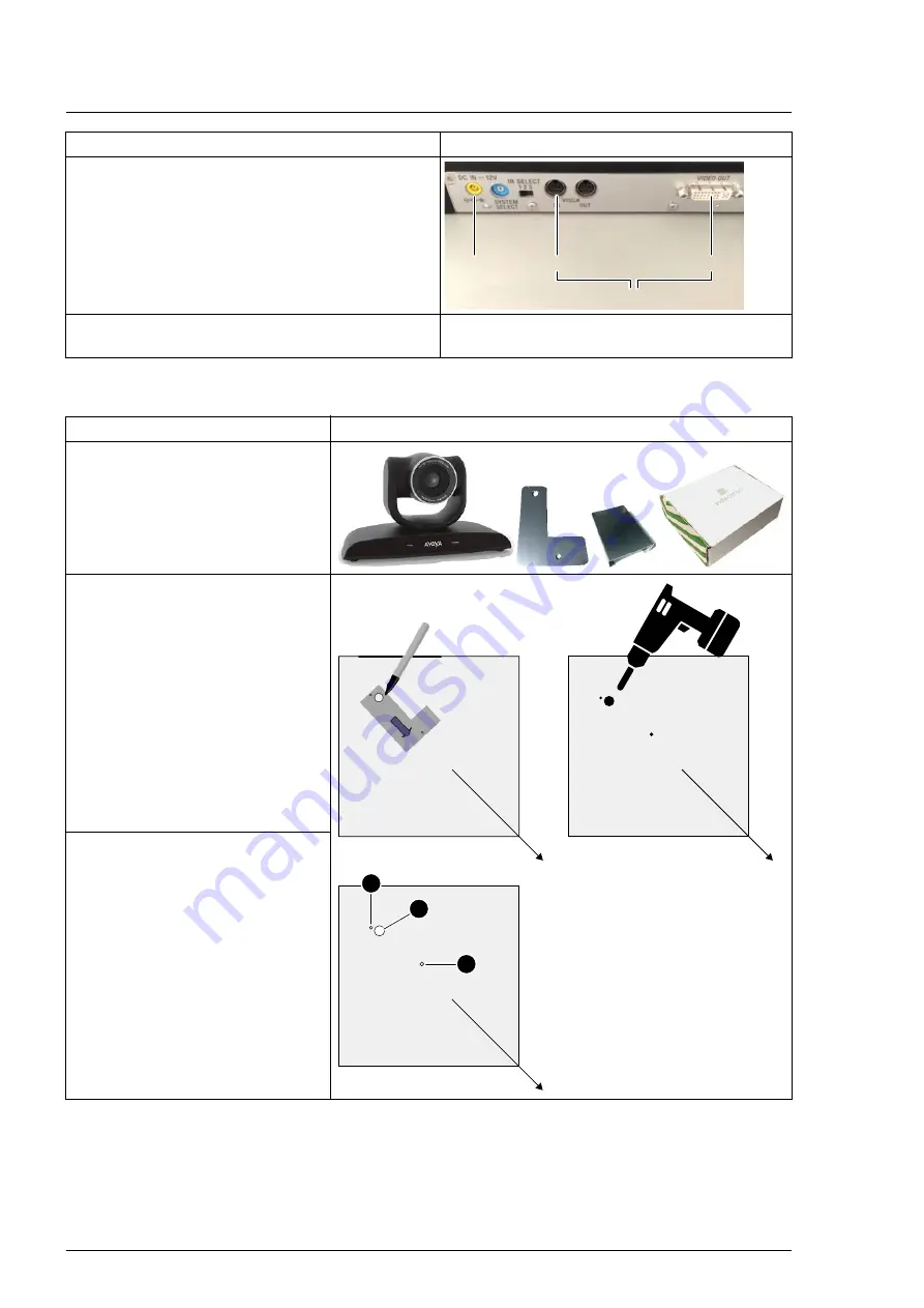
Proceed as follows to assemble the Room Cam:
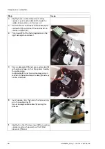
5.
On the back of the Camera cam, connect
power cable [7] to the DC 12 V power socket,
the control cable (Ctrl) to the VISCA IN
connection and the signal cable with a 180 E
Poe adapter [5] to the DVI VIDEO OUT
connection.
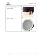
6.
Make sure Room Cam [8] is connected and
then turn it on.
Step
Image
power
Ctrl
to Truelink 4 system rack
DVI
Step
Image
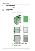
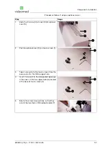
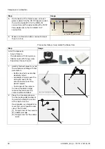
List of Components:
–
Avaya Camera
–
Counterplate with fixing screw
–
Cables cover with fixing screw
–
RoomCam Connection kit
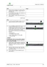
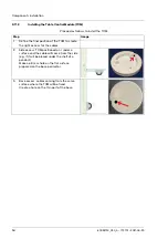
1.
Identify the best place to install
the camera according with few
parameters:
– better view (not covered by
pendants/arms),
– availability of space over the
ceiling (to easily fix the
camera and connect the
power supply),
– final scope of the camera.
In case of modular ceiling
remove the tile where the
camera will be installed.
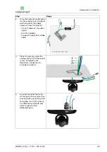
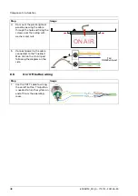
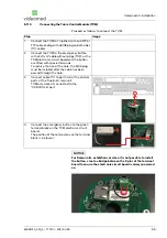
2.
Place the Counterplate over
the tile (ceiling side) and point
the arrow towards the center
of the room. Use the
Counterplate as a template to
mark the correct position and
size of the 3 holes:
[1] Fixing screw of the camera
[2] Cables passage
[3] Fixing screw for the cables
cover
3
1
2
part of the tile facing the ceiling
room
room
room
Summary of Contents for TAC500920K
Page 1: ...Service Manual Truelink 4 Video Management System ENGLISH en US...
Page 2: ...This page is intentionally blank...
Page 6: ...Truelink 4 6 80028124_030_A 773701 2021 04 29 This page is intentionally blank...
Page 113: ...This page is intentionally blank...
Page 114: ...80028124_030_A 773701 2021 04 29...


