• The power supply
Connect the power supply (4) to the POWER input and plug it into a working power outlet. Be sure to
use the power supply that came with Edit Suite. Other similar-looking power supplies, including those
with other Videonics products, may damage the unit and void the warranty.
When first connected, Edit Suite will start up automatically, turn on the LCD display, the power
indicator, and one or two of the LEDs, then run through its configuration routine. After the configuration
routine is complete, the Demo screens, the NEW menu, or the first event in your EDL will display,
depending on parameter settings and whether or not there are any events in the EDL.
• The VCR control cables
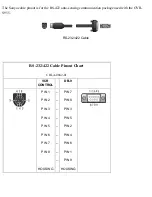
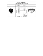
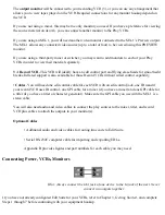
Unless your record VCR uses IR control, connect the appropriate edit control cable from the control port
of your record VCR (2) to the VCR CONTROL REC port on Edit Suite. If IR control is used, attach the
IR wand to the IR jack (5) and position the wand as shown in Chapter 3, Getting Started. Next, connect a
video monitor (1) to the Record VCR, as described in the manual that came with the VCR. You can use S-
video, composite, or RF (cable/antenna) cables to connect the Record VCR and the video monitor.
Connect one end of the appropriate control cable to Play VCR A's control jack (3), and the other end to
Edit Suite’s VCR CONTROL A port. This VCR is now Play VCR A. Repeat this step for your other Play
VCRs (6-8). Ensure that the port you select on Edit Suite matches the port to which the VCR/camcorder
is attached on the mixer/switcher.
• The output monitor’s input switch
It may be necessary to set the video monitor input switch. If the video monitor you are using has an input
selection switch, set it so it displays the correct input. For instance, if you have connected to the
monitor’s VIDEO 1 input jack, you would choose VIDEO 1 as your input. Refer to the manual that came


