background image

DE - D

eutsch - B

edienungslanleitung

13

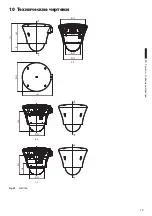
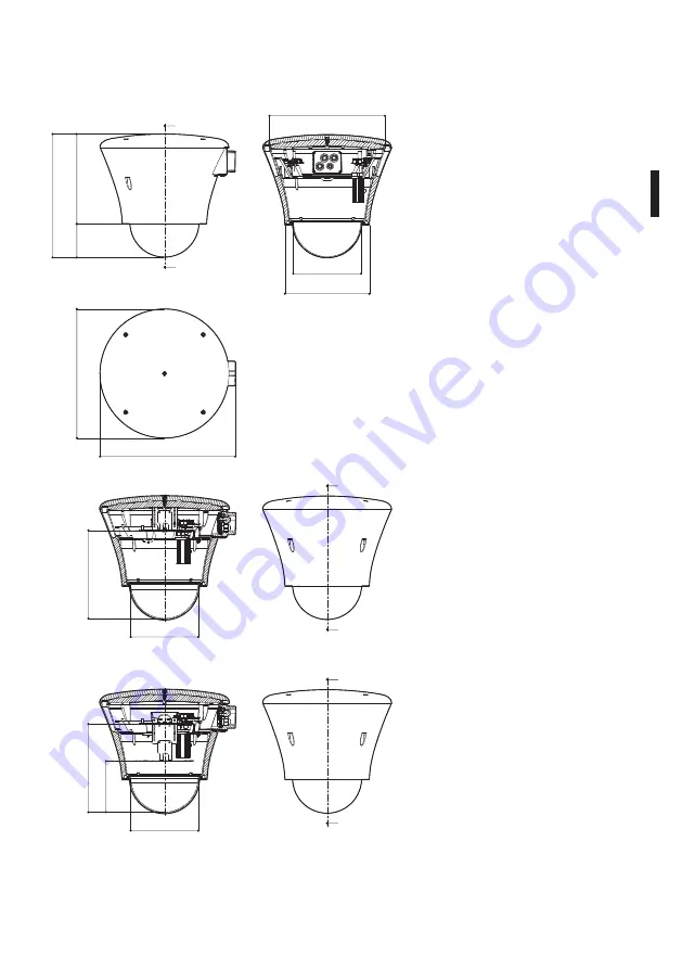
10  Technische 
Zeichnungen

240

240

138

Ø 184

Ø 184

368

Ø 314

Ø 185

Ø 230

335

244

Ø 351

91

A - A

A

B - B

C - C

B

B

C

C

A

Fig. 23 

MEDUSA

Summary of Contents for MEDUSA

Page 1: ...EN English Instructions manual IT Italiano Manuale di istruzioni FR Francais Manuel d instructions DE Deutsch Bedienungslanleitung MEDUSA Universal dome housing for discreet surveillance ...

Page 2: ......

Page 3: ...EN English Instructions manual MEDUSA Universal dome housing for discreet surveillance ...

Page 4: ... unpacking 4 5 3 Safely disposing of packaging material 4 6 Installing and assembling 5 6 1 Assembly 5 6 1 1 Assembling the plate with the cable glands 5 6 2 Installation 5 6 2 1 Installing the housing 5 6 3 Universal adapter 6 6 3 1 Wiring 9 6 3 2 Earthing 11 6 3 3 Closing the housing 11 6 3 4 Fan version 11 7 Maintaining and cleaning 12 7 1 Window and plastic cover cleaning 12 8 Disposal of wast...

Page 5: ...the appliances mentioned in this manual Furthermore the manufacturer reserves the right to modify its contents without any prior notice The documentation contained in this manual has been collected with great care the manufacturer however cannot take any liability for its use The same thing can be said for any person or company involved in the creation and production of this manual The device must...

Page 6: ...ult using the original packaging for its transport is strongly recommended 4 Identification 4 1 Product description and type designation Housing for discreet surveillance that can be used in both indoor and outdoor installations It is designed to be camouflaged with normal lighting systems Easy to install this model is able to house a range of speed domes The housing is mounted with internal cable...

Page 7: ...se operations take care not to scratch the dome 6 Installing and assembling h hOnly specialised personnel should be allowed to install and assemble the device 6 1 Assembly 6 1 1 Assembling the plate with the cable glands This section describes how to assemble the plate with cable glands that is supplied with the housing Attach the cable glands facing the direction shown taking care to tighten the ...

Page 8: ...dome from the aluminium ring by undoing the three screws Attach the adapter ring inside the housing using the 4 M4 screws supplied h hTake great care not to pinch or damage the cables there Fig 5 Pass the various wires and cables through the bracket into the inside of the housing these cables should be locked by the cable glands on the plate supplied with the housing Then close the plate using the...

Page 9: ...202E PM7 A 2 Sanyo VCC 9300P PF3 Sony SNC RZ50P PM4 A 1 SNC RZ25P PM2 H 1 Toshiba IK WB21A PM6 G 2 Tab 1 It is also necessary to use the adapter supplied with the camera Use hexagonal spacers M4x20mm PF1 PF1 PF1 PF1 PF3 PF3 PF3 PF3 PF2 PF2 PF2 PM3 PM7 PM8 PM2 PM5 PM8 PM4 PM7 PM10 PM6 PM10 PM1 PM10 PM7 PM7 PM7 PM4 PM8 PM6 PM4 PM2 PM5 PM12 PM13 PM9 PM11 PM2 PM5 PM12 PM13 PM9 PM11 PM12 PM13 PM1 PM10 ...

Page 10: ...the crimped cables to the speed dome Insert the adapter in its seating turning it to couple it with the screws M3x12mm Tighten the screws Fig 14 Fig 12 Fasten on fixed plate Fig 13 Fasten on moving plate h hThe arrow at the bottom of the adapter indicates the outside of the housing ...

Page 11: ...ype of power supply to the particular speed dome OUT 24Vac IN 230Vac Fig 15 Toroidal camera power supply IN 230Vac OUT 24Vac OUT 12Vdc OUT 24Vdc IN 100 240Vac OUT 230Vac Black Blue Fig 16 Wide range camera power supply IN 100 240Vac OUT 12 24Vdc 230Vac The voltage depends on the bought power supply ...

Page 12: ...EN English Instructions manual 10 OUT 24Vac IN 24Vac Red Fig 17 Camera power supply IN 24Vac OUT 24Vac IN 24Vac OUT 12Vdc Red Brown Fig 18 Camera power supply IN 24Vac OUT 12Vdc ...

Page 13: ...lication means the housing will lose its IP66 rating 6 3 2 Earthing If the input voltage is 230Vac earth the housing applying the two supplied cables to the cover and body using M3 6T screws and the toothed washers Complete the cabling inserting the fastons into the corresponding seats on the HEATER auxiliary board Fig 19 6 3 3 Closing the housing Disseccant salt sachet Fig 20 Take the dessicant s...

Page 14: ...th neutral soap and water h hAvoid ethyl alcohol solvents hydrogenated hydrocarbide strong acid and alkali Such products may irreparably damage the plastic surfaces 8 Disposal of waste materials n n This symbol mark and recycle system are applied only to EU countries and not applied to the countries in the other area of the world Your product is designed and manufactured with high quality material...

Page 15: ...EN English Instructions manual 13 10 Technical drawings 240 240 138 Ø 184 Ø 184 368 Ø 314 Ø 185 Ø 230 335 244 Ø 351 91 A A A B B C C B B C C A Fig 23 MEDUSA ...

Page 16: ...VIDEOTEC S p A www videotec com Printed in Italy MNVCDBH18B_1511_EN ...

Page 17: ...IT Italiano Manuale di istruzioni MEDUSA Custodia a sfera universale per sorveglianza discreta ...

Page 18: ...o e disimballaggio 4 5 3 Smaltimento in sicurezza dei materiali di imballaggio 4 6 Installazione e assemblaggio 5 6 1 Assemblaggio 5 6 1 1 Montaggio della piastrina con i pressacavi 5 6 2 Installazione 5 6 2 1 Installazione della custodia 5 6 3 Adattamento universale 6 6 3 1 Cablaggi 9 6 3 2 Cablaggio di terra 11 6 3 3 Chiusura della custodia 11 6 3 4 Versione ventilata 11 7 Manutenzione e pulizia...

Page 19: ...rio delle apparecchiature menzionate in questo manuale Si riserva inoltre il diritto di modificarne il contenuto senza preavviso Ogni cura è stata posta nella raccolta e nella verifica della documentazione contenuta in questo manuale tuttavia il produttore non può assumersi alcuna responsabilità derivante dall utilizzo della stessa Lo stesso dicasi per ogni persona o società coinvolta nella creazi...

Page 20: ...imballaggio originale per il trasporto 4 Identificazione 4 1 Descrizione e designazione del prodotto Custodia per la sorveglianza discreta utilizzabile in installazioni interne o esterne Il suo design consente la mimetizzazione in normali sistemi di illuminazione Facile da installare consente di ospitare al suo interno svariati tipi di brandeggi veloci speed domes La custodia viene montata con sup...

Page 21: ...i fare attenzione a non graffiare la cupola 6 Installazione e assemblaggio h hL installazione e l assemblaggio vanno eseguiti solo da personale specializzato 6 1 Assemblaggio 6 1 1 Montaggio della piastrina con i pressacavi Questo paragrafo descrive il montaggio della piastrina con i pressacavi fornita nella dotazione della custodia Applicare i pressacavi nel verso indicato in figura avendo cura d...

Page 22: ...e dall anello in alluminio svitando le tre viti Fissare l anello adattatore all interno della custodia tramite le 4 viti M4 fornite in dotazione h hAttenzione a non pizzicare o rovinare i cablaggi presenti Fig 5 Passare i vari cablaggi attraverso la staffa fino a giungere all interno della custodia tali cavi dovranno essere bloccati con i pressacavi della piastrina in dotazione Procedere quindi al...

Page 23: ... 2 Sanyo VCC 9300P PF3 Sony SNC RZ50P PM4 A 1 SNC RZ25P PM2 H 1 Toshiba IK WB21A PM6 G 2 Tab 1 È necessario utilizzare anche l adattamento fornito in dotazione con la telecamera Utilizzare distanziali esagonali M4x20mm PF1 PF1 PF1 PF1 PF3 PF3 PF3 PF3 PF2 PF2 PF2 PM3 PM7 PM8 PM2 PM5 PM8 PM4 PM7 PM10 PM6 PM10 PM1 PM10 PM7 PM7 PM7 PM4 PM8 PM6 PM4 PM2 PM5 PM12 PM13 PM9 PM11 PM2 PM5 PM12 PM13 PM9 PM11 ...

Page 24: ...emente crimpati alla speed dome Inserire l adattamento nella sede agganciandolo con una rotazione alle viti M3x12mm Serrare le viti Fig 14 Fig 12 Fissaggio su piastra fissa Fig 13 Fissaggio su piastra mobile h hLa freccia nella parte bassa dell adattamento deve indicare la parte esterna della custodia ...

Page 25: ...imentazione della speed dome installata OUT 24Vac IN 230Vac Fig 15 Alimentatore toroidale per telecamera IN 230Vac OUT 24Vac OUT 12Vdc OUT 24Vdc IN 100 240Vac OUT 230Vac Nero Blu Fig 16 Alimentatore wide range per telecamera IN 100 240Vac OUT 12 24Vdc 230Vac La tensione dipende dal tipo di alimentatore acquistato ...

Page 26: ...IT Italiano Manuale di istruzioni 10 OUT 24Vac IN 24Vac Rosso Fig 17 Alimentatore per telecamera IN 24Vac OUT 24Vac IN 24Vac OUT 12Vdc Marrone Rosso Fig 18 Alimentatore per telecamera IN 24Vac OUT 12Vdc ...

Page 27: ...caduta della caratteristica IP66 della custodia 6 3 2 Cablaggio di terra In caso di tensione in ingresso 230Vac eseguire la messa a terra della custodia applicando i due cablaggi in dotazione su coperchio e corpo tramite le viti M3 6T e le rosette dentellate Completare il cablaggio inserendo i faston negli alloggiamenti previsti della schedina di appoggio HEATER Fig 19 6 3 3 Chiusura della custodi...

Page 28: ...Sono da evitare alcool etilico solventi idrocarburi idrogenati acidi forti e alcali L utilizzo di detti prodotti danneggia in modo irreparabile la superficie delle parti in plastica 8 Smaltimento dei rifiuti n n Questo simbolo e il sistema di riciclaggio sono validi solo nei paesi dell EU e non trovano applicazione in altri paesi del mondo Il vostro prodotto è stato costruito da materiali e compon...

Page 29: ...IT Italiano Manuale di istruzioni 13 10 Disegni tecnici 240 240 138 Ø 184 Ø 184 368 Ø 314 Ø 185 Ø 230 335 244 Ø 351 91 A A A B B C C B B C C A Fig 23 MEDUSA ...

Page 30: ...VIDEOTEC S p A www videotec com Printed in Italy MNVCDBH18B_1511_IT ...

Page 31: ...FR Français Manuel d instructions MEDUSA Caisson dôme universel pour surveillance discrète ...

Page 32: ...enu et déballage 4 5 3 Élimination sans danger des matériaux d emballage 4 6 Installation et assemblage 5 6 1 Assemblage 5 6 1 1 Montage de la platine avec les presse câbles 5 6 2 Installation 5 6 2 1 Installation du caisson 5 6 3 Adaptateur universel 6 6 3 1 Câblages 9 6 3 2 Câblage de terre 11 6 3 3 Fermeture de le caisson 11 6 4 Version ventilée 11 7 Entretien et nettoyage 12 7 1 Entretiens de ...

Page 33: ... utilisation non appropriée des appareils mentionnés dans ce manuel On réserve en outre le droit d en modifier le contenu sans préavis La documentation contenue dans ce manuel a été rassemblée et vérifiée avec le plus grand soin cependant le producteur ne peut pas s assumer aucune responsabilité dérivante de l emploi de celle là La même chose vaut pour chaque personne ou société impliquées dans la...

Page 34: ...inal pour le transport 4 Identification 4 1 Description et désignation du produit Caisson pour la surveillance discrète qui peut être utilisé dans des installations internes ou externes et conçu pour se camoufler dans les systèmes d illumination courants D installation simple ce modèle permet d accueillir différents types de tourelles rapides speed domes à l intérieur Le caisson est installé avec ...

Page 35: ...upport Fig 4 h hAttention à ne pas rayer la coupole durant les opérations 6 Installation et assemblage h hL installation et l assemblage doivent exclusivement être effectués par un personnel spécialisé 6 1 Assemblage 6 1 1 Montage de la platine avec les presse câbles Ce paragraphe décrit les opérations de montage de la platine avec presse câbles fournie avec le caisson Appliquer les presse câbles ...

Page 36: ...ter l adaptateur universel pour le speed dome de la bague en aluminium en desserrant les trois vis Fixer la bague d adaptation à l intérieur du caisson au moyen des 4 vis M4 fournies h hNe pas pincer ni endommager les câblages Fig 5 Faire passer les câblages au travers de l étrier jusqu à l intérieur du caisson les câbles doivent être bloqués au moyen des presse câbles de la platine fournie Fermer...

Page 37: ...A 2 Sanyo VCC 9300P PF3 Sony SNC RZ50P PM4 A 1 SNC RZ25P PM2 H 1 Toshiba IK WB21A PM6 G 2 Tab 1 Il est nécessaire d utiliser également l adaptateur fourni avec la caméra Utiliser des entretoises hexagonales M4x20mm PF1 PF1 PF1 PF1 PF3 PF3 PF3 PF3 PF2 PF2 PF2 PM3 PM7 PM8 PM2 PM5 PM8 PM4 PM7 PM10 PM6 PM10 PM1 PM10 PM7 PM7 PM7 PM4 PM8 PM6 PM4 PM2 PM5 PM12 PM13 PM9 PM11 PM2 PM5 PM12 PM13 PM9 PM11 PM12...

Page 38: ...onnecter les câbles sertis au speed dome Insérer l adaptateur dans le logement en le fixant par rotation aux vis M3x12mm Serrer les vis Fig 14 Fig 12 Fixage sur plaque fixe Fig 13 Fixage sur plaque mobile h hLa flèche en bas de l adaptateur indique la partie externe du caisson ...

Page 39: ...ype d alimentation du speed dome installé OUT 24Vac IN 230Vac Fig 15 Alimentation toroïdale pour caméra IN 230Vac OUT 24Vac OUT 12Vdc OUT 24Vdc IN 100 240Vac OUT 230Vac Noir Bleu Fig 16 Alimentation wide range pour caméra IN 100 240Vac OUT 12 24Vdc 230Vac La tension dèpend du type d alimentation achetèe ...

Page 40: ...FR Francais Manuel d instructions 10 OUT 24Vac IN 24Vac Rouge Fig 17 Alimentation pour caméra IN 24Vac OUT 24Vac IN 24Vac OUT 12Vdc Rouge Marron Fig 18 Alimentation pour caméra IN 24Vac OUT 12Vdc ...

Page 41: ...a caractéristique IP66 du caisson 6 3 2 Câblage de terre En cas de tension en entrée de 230Vac effectuer la mise à terre du caisson en appliquant les deux câblages fournis sur le couvercle et la structure au moyen de vis M3 6T et de rondelles dentelées Terminer le câblage en insérant les Fastons dans les logements prévus dans la carte de support HEATER Fig 19 6 3 3 Fermeture de le caisson Insérer ...

Page 42: ...neutres dilués avec de l eau h hOn doit éviter alcool éthylique solvants hydrocarbures hydrogénés acides forts et alcali L emploi de ce type de produits abîme d une façon irréparable les surfaces en plastique 8 Élimination des déchets n n Ce symbole et le système de recyclage ne sont appliqués que dans les pays UE et non dans les autres pays du monde Votre produit est conçu et fabriqué avec des ma...

Page 43: ...FR Francais Manuel d instructions 13 10 Dessins techniques 240 240 138 Ø 184 Ø 184 368 Ø 314 Ø 185 Ø 230 335 244 Ø 351 91 A A A B B C C B B C C A Fig 23 MEDUSA ...

Page 44: ...VIDEOTEC S p A www videotec com Printed in Italy MNVCDBH18B_1511_FR ...

Page 45: ...DE Deutsch Bedienungslanleitung MEDUSA Universalkugelgehäuse für diskrete Videoüberwachung ...

Page 46: ...ernen der Verpackung 4 5 3 Sichere Entsorgung der Verpackungsmaterialien 4 6 Installation und Zusammenbau 5 6 1 Zusammenbau 5 6 1 1 Montage des Plättchens mit Kabelschellen 5 6 2 Installation 5 6 2 1 Gehäuseinstallation 5 6 3 Allzweck Adapter 6 6 3 1 Verkabelungen 9 6 3 2 Erdverkabelung 11 6 3 3 Das Gehäuse verschliessen 11 6 3 4 Belüftete Ausführung 11 7 Wartung und Reinigung 12 7 1 Reinigung des...

Page 47: ...n diesem Handbuch erwähnten Geräte entstanden ist Ferner behält er sich das Recht vor den Inhalt ohne Vorkündigung abzuändern Die Dokumentation in diesem Handbuch wurde sorgfältig ausgeführt und überprüft dennoch kann der Hersteller keine Haftung für die Verwendung übernehmen Dasselbe gilt für jede Person oder Gesellschaft die bei der Schaffung oder Produktion von diesem Handbuch miteinbezogen ist...

Page 48: ...kzusenden 4 Identifizierung 4 1 Beschreibung und Bezeichnung des Produktes Gehäuse das für die unauffällige Überwachung in Anlagen des Innen und Außenbereiches geeignet ist Es ist so entworfen dass es sich unsichtbar in normale Beleuchtungssysteme einpasst Dieses installationsfreundliche Modell kann unterschiedliche Typen von schnellen Schwenk Neige Köpfen Speed Domes in seinem Innern aufnehmen Da...

Page 49: ...er Schritte achten Sie bitte darauf dass die Kugel nicht verkratzt 6 Installation und Zusammenbau h hInstallation und Zusammenbau sind Fachleuten vorbehalten 6 1 Zusammenbau 6 1 1 Montage des Plättchens mit Kabelschellen In diesem Abschnitt wird beschrieben wie das im Lieferumfang des Gehäuses enthaltene Plättchen mit Kabelschellen zu montieren ist Die Kabelschellen in der Richtung anbringen die i...

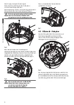
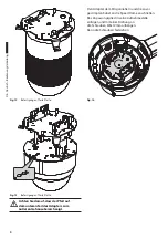
Page 50: ...al Adapter für die Speed Dome durch Ausdrehen der drei Schrauben vom Aluminiumring entfernen Den Adapterring mit den 4 zur Lieferung gehörenden Schrauben M4 im Innern des Gehäuses fixieren h hEs muss genau darauf geachtet werden dass die vorhandenen Kabel nicht eingeklemmt oder beschädigt werden Fig 5 Die einzelnen Kabel durch den Bügel ins Gehäuseinnere führen und mit den Kabelschellen des mitgel...

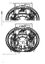
Page 51: ... VCC 9300P PF3 Sony SNC RZ50P PM4 A 1 SNC RZ25P PM2 H 1 Toshiba IK WB21A PM6 G 2 Tab 1 Auch das im Lieferumfang der Kamera enthaltene AnpassungsgliedÈ ist zu verwenden Bitte sechskantige Distanzstücke M4x20mm verwenden PF1 PF1 PF1 PF1 PF3 PF3 PF3 PF3 PF2 PF2 PF2 PM3 PM7 PM8 PM2 PM5 PM8 PM4 PM7 PM10 PM6 PM10 PM1 PM10 PM7 PM7 PM7 PM4 PM8 PM6 PM4 PM2 PM5 PM12 PM13 PM9 PM11 PM2 PM5 PM12 PM13 PM9 PM11 ...

Page 52: ...en Das Anpassungsglied in seine Aufnahmestelle einfügen und mit einer Drehung an die Schrauben M3x12mm anhängen Dann die Schrauben festziehen Fig 14 Fig 12 Befestigung auf feste Platte Fig 13 Befestigung auf feste Platte h hAchten Sie darauf dass der Pfeil auf dem unteren Teil des Adapters zum äußeren Gehäusebereich zeigt ...

Page 53: ...nnungsversorgung der installierten Speed Dome abhängen OUT 24Vac IN 230Vac Fig 15 Toroidales Kameranetzteil IN 230Vac OUT 24Vac OUT 12Vdc OUT 24Vdc IN 100 240Vac OUT 230Vac Schwarz Blau Fig 16 Wide Range Kameranetzteil IN 100 240Vac OUT 12 24Vdc 230Vac Die Spannung hängt vom bezogenen Kameranetzteilmodell ab ...

Page 54: ...DE Deutsch Bedienungslanleitung 10 OUT 24Vac IN 24Vac Rot Fig 17 Kameranetzteil IN 24Vac OUT 24Vac IN 24Vac OUT 12Vdc Rot Braun Fig 18 Kameranetzteil IN 24Vac OUT 12Vdc ...

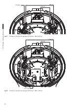
Page 55: ...hutzart IP66 des Gehäuses nicht mehr gegeben 6 3 2 Erdverkabelung Bei einer Eingangsspannung von 230Vac muss das Gehäuse geerdet werden Dazu die beiden zum Lieferumfang gehörenden Kabel mit Schrauben M3 6T und Zahnscheiben an Abdeckung und Korpus anbringen Anschließend können sie in die zugehörigen Flachstecker eingefügt werden die auf der Hilfsplatine HEATER sitzen Fig 19 6 3 3 Das Gehäuse versch...

Page 56: ...fe starke Säuren und Alkali Diese Produkte können die Kunststoffoberfläche beschädigen 8 Müllentsorgungsstellen n n Dieses Symbol und das entsprechende Recycling System gelten nur für EULänder und finden in den anderen Ländern der Welt keine Anwendung Ihr Produkt wurde entworfen und hergestellt mit qualitativ hochwertigen Materialien und Komponenten die recycelt und wiederverwendet werden können D...

Page 57: ...DE Deutsch Bedienungslanleitung 13 10 Technische Zeichnungen 240 240 138 Ø 184 Ø 184 368 Ø 314 Ø 185 Ø 230 335 244 Ø 351 91 A A A B B C C B B C C A Fig 23 MEDUSA ...

Page 58: ...VIDEOTEC S p A www videotec com Printed in Italy MNVCDBH18B_1511_DE ...

Page 59: ...RU Русский Учебник инструкции MEDUSA Универсальная кожухи сфера для видеонаблюдения ...

Page 60: ... 3 Безопасная утилизация упаковочных материалов 4 6 Установка и сборка 5 6 1 Сборка 5 6 1 1 Монтаж пластины с кабельными муфтами 5 6 2 Установка 5 6 2 1 Установка предохранительного кожуха 5 6 3 Универсальный адаптер 6 6 3 1 Кабельная проводка 9 6 3 2 Проводка заземления 11 6 3 3 Закрытие корпуса 11 6 3 4 Версия с вентиляцией 11 7 Техническое обслуживание и очистка 12 7 1 Очистка стекла и пластмас...

Page 61: ...начению и без соблюдения инструкций изложенных в данном руководстве Производитель также оставляет за собой право на внесение изменений без предварительного уведомления При составлении и проверке документации настоящего руководства были включены все необходимые меры предосторожности тем не менее производитель снимает с себя ответственность за результаты ее использования То же самое относится к любо...

Page 62: ... оригинальную упаковку для транспортировки 4 Идентификация 4 1 Описание и назначение типа Кожух для дискретного наблюдения который можно использовать для внутренних и внешних установок Его дизайн обеспечивает маскировку в нормальных системах освещения Простой в установке внутри него могут разместиться разнообразные быстрые поворотные устройства скоростные купольные камеры Кожух устанавливается на ...

Page 63: ...комплекте с опорой Fig 4 h hВо время операций будьте внимательны чтобы не поцарапать купол 6 Установка и сборка h hУстановка и сборка оборудования должны выполняться только квалифицированным персоналом 6 1 Сборка 6 1 1 Монтаж пластины с кабельными муфтами В этом параграфе описывается монтаж пластины с кабельными муфтами поставляемой в комплекте с кожухом Разместить пластину на плоскость в указанно...

Page 64: ... три винта Закрепить кольцо адаптера внутри кожуха с помощью четырех винтов М4 поставляемых в комплекте h hБудьте осторожны чтобы не прищемить или не повредить кабельную проводку Fig 5 Провести различные кабели через кронштейн до достижения внутренней части кожуха эти кабели должны быть заблокированы с помощью кабельных муфт пластины поставляемой в комплекте Далее закрыть пластину с помощью постав...

Page 65: ... 2 WV CS9500 PF1 WV NS202E PM7 A 2 Sanyo VCC 9300P PF3 Sony SNC RZ50P PM4 A 1 SNC RZ25P PM2 H 1 Toshiba IK WB21A PM6 G 2 Tab 1 Вы также должны использовать регулировку который поставляется с камерой Используйте прокладки M4x20mm PF1 PF1 PF1 PF1 PF3 PF3 PF3 PF3 PF2 PF2 PF2 PM3 PM7 PM8 PM2 PM5 PM8 PM4 PM3 PM3 PM7 PM10 PM6 PM6 PM6 PM10 PM1 PM10 PM7 PM7 PM4 PM4 PM7 PM7 PM4 PM8 PM9 PM11 PM2 PM5 PM2 PM5...

Page 66: ...бели к скоростной купольной камере Монтировать всё внутрь кожуха осторожно вставив в соответствующие гнёзда и закрепив три поставленных винта M3 6T Fig 14 Fig 12 Крепление к неподвижной пластине Fig 13 Крепление к подвижной пластине h hСтрелка в нижней части адаптера должна указывать внешнюю часть кожуха ...

Page 67: ... скоростной купольной камеры OUT 24Vac IN 230Vac Fig 15 Тороидальный блок питания для телекамеры ВХ 230 В пер т ВЫХ 24 В пер тока OUT 12Vdc OUT 24Vdc IN 100 240Vac OUT 230Vac Черный Синий Fig 16 Блок питания wide range для телекамеры ВХ 100 240 В пер т ВЫХ 12 24 В пост т 230 В пер т Напряжение зависит от типа приобретённого источника питания ...

Page 68: ...ик инструкции 10 OUT 24Vac IN 24Vac Красный Fig 17 Источник питания для телекамеры ВХ 24 В пер т ВЫХ 24 В пер т IN 24Vac OUT 12Vdc Коричневый Красный Fig 18 Источник питания для телекамеры ВХ 24 В пер т ВЫХ 12 В пост т ...

Page 69: ...чёт за собой ухудшение характеристики IP66 кожуха 6 3 2 Проводка заземления В случае напряжения на входе 230 В пер т выполнить заземление кожуха установив два кабелепровода входящие в комплект на крышке и корпусе с помощью винтов M3 6T и зубчатых шайб Выполнить проводку вставив соединитель с плоскими контактами в предусмотренные для этого отверстия на опорной спинке нагревателя Fig 19 6 3 3 Закрыт...

Page 70: ... 7 1 Очистка стекла и пластмассовых частей Рекомендуется нейтральное мыло разведенное в воде h hИзбегать применение этилового спирта растворителей гидрированных углеводородов сильных кислот и щелочей Использование названных продуктов наносит непоправимый вред пластмассовым поверхностям 8 Утилизация отходов n n Данный символ и система переработки действительны только в странах ЕС и не применяются в...

Page 71: ...RU Русский Учебник инструкции 13 10 Технические чертежи 240 240 138 Ø 184 Ø 184 368 Ø 314 Ø 185 Ø 230 335 244 Ø 351 91 A A A B B C C B B C C A Fig 23 MEDUSA ...

Page 72: ...VIDEOTEC S p A www videotec com Printed in Italy MNVCDBH18B_1511_RU ...

Page 73: ......

Page 74: ...rance Tel 33 1 60491816 Fax 33 1 69284736 Email info fr videotec com Asia Pacific Videotec HK Ltd Flat 8 19 F On Dak Industrial Building No 2 6 Wah Sing Street Kwai Chung New Territories Hong Kong Tel 852 2333 0601 Fax 852 2311 0026 Email info hk videotec com Americas Videotec Security Inc Gateway Industrial Park 35 Gateway Drive Suite 100 Plattsburgh NY 12901 U S A Tel 1 518 825 0020 Fax 1 518 82...

Reviews: