Instruc
tion manual - English - EN
3
MNVKUPTJBUL_1822_EN
6 Installation
CAUTION! Device installation and
maintaining must be performed by
specialist technical staff only.
6.1 Connections
Electrical connections must be performed
with the power supply disconnected and
the circuit-breaker open.
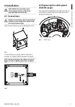
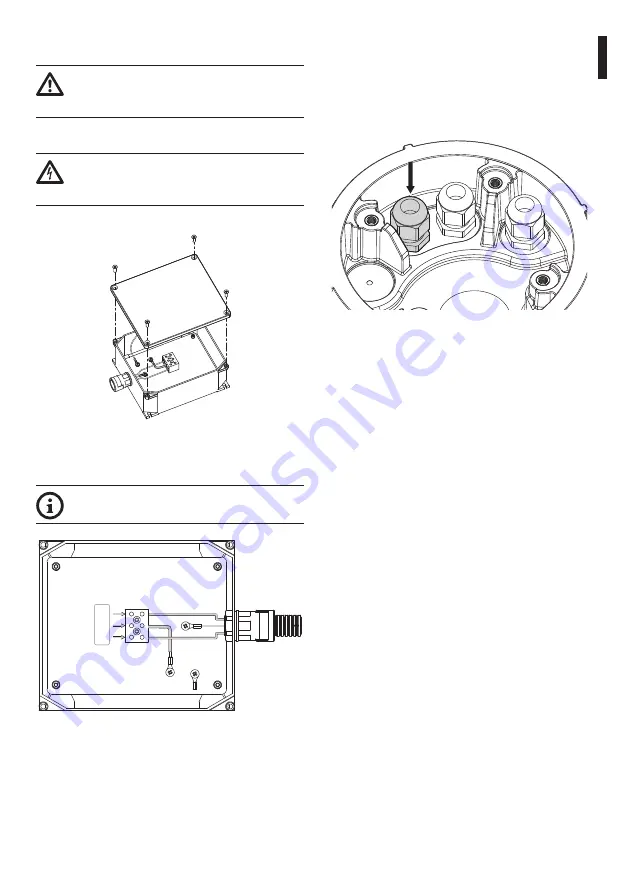
Open the box taking care not to damage the seals.
Fig.
1
Connect the power supply cables to the electric
network, according to that indicated in the figure.
Nominal section of the cables used: from
0.75mm² (18AWG) up to 4mm² (12AWG).
a
N
L
Fig.
2
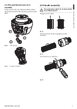
6.2 Replacing the cable gland
(ULISSE range)
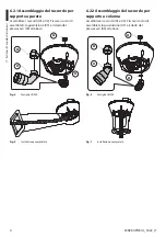
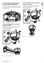
Disassemble the highlighted cable gland to replace
it with the provided connector, taking care not to
damage the fixing nut.
Fig.
3
ULISSE range.
Summary of Contents for UPTJBUL
Page 2: ......
Page 35: ...RU 1 MNVKUPTJBUL_1822_RU UPTJBUL 1 1 1 INFO 2 3 4 2 2...
Page 36: ...RU 2 MNVKUPTJBUL_1822_RU 4 4 1 ULISSE UL 4 2 5 5 1 5 2 45 90 5 3 5 4 5 4 1...
Page 37: ...RU 3 MNVKUPTJBUL_1822_RU 6 6 1 1 0 75mm 18AWG 4mm 12AWG a N L 2 6 2 ULISSE 3 C ULISSE...
Page 40: ...RU 6 MNVKUPTJBUL_1822_RU 6 4 ULISSE2 13 C ULISSE2 6 4 1 01 02 03 01 02 03 14 C ULISSE2 15...
Page 41: ...RU 7 MNVKUPTJBUL_1822_RU 6 4 2 01 02 03 01 02 03 16 C ULISSE2 17 6 5 UL 18 19 20...
Page 43: ......


