background image

MDCS2


U

SER

M

ANUAL


©

2004


V

IDERE 

D

ESIGN


10 

5 Lenses 

The MDCS2 uses standard C/CS mount lenses.   

Lenses are characterized optically by imager size, F number, and focal 
length.  Following subsections discuss the choice of these values. 

5.1 Changing 

Lenses 

To insert a lens, place it back end on the lens holder opening as straight as 
possible, and gently turn it clockwise (looking down at the lens) until it 
engages the threads of the lens holder.  If you encounter a lot of resistance, 
you may be cross-threading the lens.  Forcing it on will damage the plastic 
lens holder threads. 

Once the threads are engaged, continue screwing it on until it snugs down 
on the lens holder. 

Removing the lens is the reverse process: unscrew the lens counter-
clockwise.   

Normal care should be used in taking care of the lenses, as with lenses for 
any good-quality camera.   

5.2  Cleaning the Imagers 

It should not be necessary to clean the imagers, since they are sealed off by 
an IR filter inside the lens mount. 

If dirt and dust are present on the IR filter surface, they can be cleaned in 
the same manner as a lens.  Wet a non-abrasive optic cleaning tissue with a 
small amount of methyl alcohol or similar lens-cleaning solvent, and wipe 
the imager glass surface gently.  Dry with a similar tissue. 

5.3 Imager 

Size 

The 

imager size

 is the largest size of imager that can be covered by the lens.  

For the MDCS2, the lens must be for an imager 1/2” or larger.   

5.4 F 

Number 

The 

F number

 is a measure of the light-gathering ability of a lens.  The 

lower the F number, the better it is at pulling in light, and the better the 
MDCS2 will see in low-illumination settings.  For indoor work, an F 
number of 1.8 is acceptable, and 1.4 is even better.  For outdoors, higher F 
numbers are fine.  C/CS mount lenses typically have adjustable iris and 
focus rings. 

5.5 Focal 

Length 

The 

focal length

 is the distance from the lens virtual viewpoint to the 

imager.  It defines how large an angle the imager views through the lens.  
The focal length is a primary determinant of the performance of a camera 
system.  It affects two important aspects of the system: how wide a field of 
view the system can see, and how good the resolution of the scene is.  
Unfortunately there’s a tradeoff here.  A wide-angle lens (short focal 
length) gives a great field of view, but causes a drop in resolution.  A 
telephoto lens (long focal length) can only see a small field of view, but 
gives better resolution.  So the choice of lens focal length usually involves a 
compromise.  In typical situations, one usually chooses the focal length 
based on the narrowest field of view acceptable for an application, and then 
takes whatever resolution comes with it. 

5.6  Field of View 

The field of view is completely determined by the focal length, given a 
fixed imager.  The formulas for the FOV in horizontal and vertical 
directions are: 

)

/

328

.

3

arctan(

2

f

HFOV

=


)

/

496

.

2

arctan(

2

f

VFOV

=


where 

f

 is in millimeters.  For example, a 6.0 mm lens yields a horizontal 

FOV of 58 degrees.  The following table shows the FOV for some standard 
focal lengths. 


Summary of Contents for MDCS2

Page 1: ...MDCS2 USER S MANUAL 2004 VIDERE DESIGN 1 MDCS2 Digital Video Camera User s Manual 2004 Videre Design...

Page 2: ...0 5 2 Cleaning the Imagers 10 5 3 Imager Size 10 5 4 F Number 10 5 5 Focal Length 10 5 6 Field of View 10 6 1394 Interface 12 6 1 IEEE 1394 Cable 12 6 2 IEEE 1394 Host Interface 12 6 3 Supplying Power...

Page 3: ...ese drivers are included in a Software Developer s Kit which is bundled with the devices Using the libraries in the kit you can quickly integrate MDCS2 video acquisition into your own applications wri...

Page 4: ...there is a MDCS2 present If not go back to software installation Section Error Reference source not found and follow the instructions for configuring the correct capture library Pull down the Input ch...

Page 5: ...no user settable switches on the MDCS2 3 1 Hardware Schematic Figure 3 2 shows the design of the internal hardware of the MDCS2 In the imager module a Micron MT9M001 imager of size 1280x1024 pixels di...

Page 6: ...en streaming video at the same frame rate they are synchronized so that they capture images at the same time Each IEEE 1394 PC Card or PCI Card defines a separate IEEE 1394 bus The two or three ports...

Page 7: ...ting the number of bytes in each frame because there are blank cycles on the bus when no data is being transmitted even though the bandwidth is reserved Thus it makes no difference whether the rate is...

Page 8: ...Desktop PCs supply power to the bus laptops do not See Section 6 for information about cabling and power for the IEEE 1394 bus 4 1 2 Linux Hardware and Driver Installation Linux kernels 2 4 or 2 6 ker...

Page 9: ...DERE DESIGN 9 libdcap so and dCamera lib dll are the capture libraries for Linux and MS Windows respectively There are several sample applications see the DCAM Digital Camera Capture Software User s M...

Page 10: ...ger 5 4 F Number The F number is a measure of the light gathering ability of a lens The lower the F number the better it is at pulling in light and the better the MDCS2 will see in low illumination se...

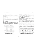
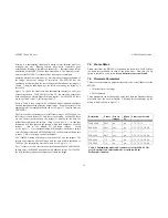
Page 11: ...USER S MANUAL 2004 VIDERE DESIGN 11 Lens focal length Horizontal FOV Vertical FOV 3 5 mm 87 deg 71 deg 6 0 58 45 12 0 31 25 Table 5 1 Horizontal and vertical field of view for different lens focal le...

Page 12: ...CIA cards do not have the capability of supplying power and come with an adapter for supplying power to the 1394 cable through a wall transformer Any 1394 card is suitable as long as it conforms to OH...

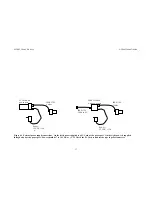
Page 13: ...Card with a power port On the right power is supplied through a hub with a power port Power should be 7 to 16 VDC at 2 W Check the PC Card or hub for the type of power connector IEEE 1394 Cables Power...

Page 14: ...nts of the three colors red green blue affects the appearance of the color image Many color CCD imagers have attached processors that automatically balance the offsets among these colors to produce an...

Page 15: ...possible for your application without having to use gain This will increase the depth of field and give better optical performance Indoors the iris usually is fully open Outdoors in bright conditions...

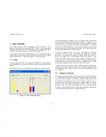
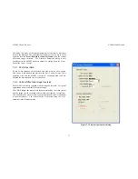
Page 16: ...on the imager which then transmits a 640x480 imager this is the default for full frame images Using SetSample 1 2 means that binning will take place on the host In this case the imager transmits all...

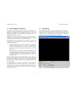
Page 17: ...This choice is downloaded and stored in the device and will cause 50 Hz operation every time the MDCS2 is accessed To change back to 60 Hz uncheck the box and again save it to the device 7 6 2 Vertica...

Page 18: ...CS2 USER S MANUAL 2004 VIDERE DESIGN 18 8 Interface Software API Please see the DCAM Digital Camera Capture Software User s Manual for information about the software API for capturing and saving image...

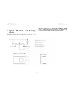
Page 19: ...Diagram The diagram below shows the physical dimensions for the MDCS2 C The larger hole is threaded for a 20 machine screw standard tripod mounting screw The two smaller holes are threaded for 6 32 ma...

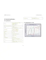
Page 20: ...Bayer color pattern Frame Rates 3 75 7 5 15 30 60 Hz 3 125 6 5 12 5 25 50 Hz Max 15 Hz at 1280x960 Exposure 1 line time to full frame Gain 0 18 dB Sensitivity 2 1 V lux sec monochrome S N 45 dB no gai...

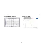
Page 21: ...MDCS2 USER S MANUAL 2004 VIDERE DESIGN 21 10 3 Imager Response Monochrome 10 4 Filter Transmittance...

Page 22: ...NUAL 2004 VIDERE DESIGN 22 11 Technical Support For technical support please contact Videre Design by email or FAX Videre Design 865 College Avenue Menlo Park CA 94025 Fax 650 323 3646 Email support v...

Reviews: