background image

VIDEX VproX-100 

(2 DOOR, 100 KEY SYSTEM) 


4

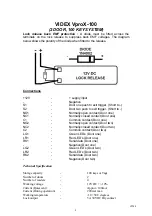
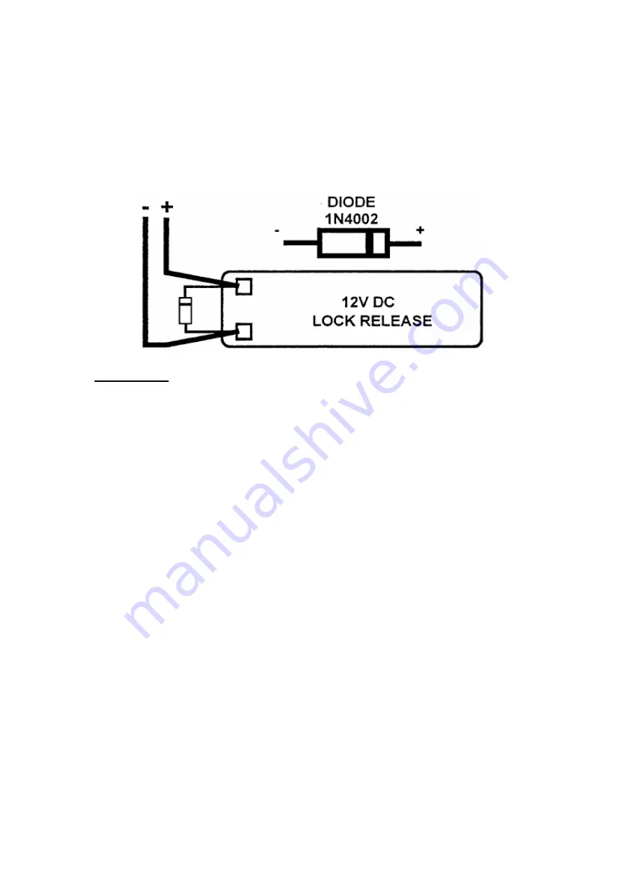
Lock release back EMF protection : 

A diode must be fitted across the 

terminals on the lock release to suppress back EMF voltages. The diagram 
below shows the polarity of the diode when fitted to the release. 
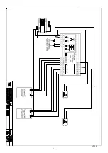


Connections


+12V 

  -  + 

supply 

input 

-   -  Negative 
S1 


Door one push to exit trigger. (Short to -) 

S2 


Door two push to exit trigger. (Short to -) 

NO1   


Normally open contact (Door one) 

NC1   


Normally closed contact (Door one) 

C1 

  -  Common 

contact 

(Door 

one) 

NO2   


Normally open contact (Door two) 

NC2   


Normally closed contact (Door two) 

C2 

  -  Common 

contact 

(Door 

two) 

LG1 

  -  Green 

LED’s 

(Door 

one) 

LR1 

  -  Red 

LED’s 

(Door 

one) 

RK1 

  -  Serial 

data 

(Door 

one) 

-   -  Negative 

(Door 

one) 

LG2 

  -  Green 

LED’s 

(Door 

two) 

LR2 

  -  Red 

LED’s 

(Door 

two) 

RK2 

  -  Serial 

data 

(Door 

two) 

-   -  Negative 

(Door 

two) 


Technical Specification 

 
Storage capacity 


100 keys or Tags 

Number 

of 

doors 

 -   2 

Number 

of 

readers 

 -   4 

Working voltage 


12V DC +/- 10% 

Current 

(Quiescent) 

 -   Approx. 

100mA 

Current (During operation) 


200mA max. 

Working temperature   


-10 +50 C degrees 

Lock 

output 

  -   5A 

30VDC 

Dry 

contact 

VP100

Summary of Contents for VproX-100

Page 1: ...o access the programming menu Program up to 100 unique keys or Tags with door access options To modify the settings and parameters of a stored key Delete one or more keys or Tags Program each door relay time 1 to 99 seconds INITIALISATION When the installation has been completed carried out in accordance with the supplied wiring diagram the system can be powered up and programmed following the Vpr...

Page 2: ...umber of the 1st free location if available press enter to confirm or select another number by pressing the up arrow keys NOTE If when you press enter you hear a long beep that number is already taken and you must choose another number After pressing enter you may select using the up arrow keys which door the key has access to Default both doors on The doors are indicated by the decimal points on ...

Page 3: ...3 VP100 ...

Page 4: ...1 Normally closed contact Door one C1 Common contact Door one NO2 Normally open contact Door two NC2 Normally closed contact Door two C2 Common contact Door two LG1 Green LED s Door one LR1 Red LED s Door one RK1 Serial data Door one Negative Door one LG2 Green LED s Door two LR2 Red LED s Door two RK2 Serial data Door two Negative Door two Technical Specification Storage capacity 100 keys or Tags...

Page 5: ... CPU with both the Read head connected and disconnected The LED s on the read head are on but do not change state when a key is presented Check terminal RK1 2 for continuity and possible shorts to other wires Reader head is going green when a key or Tag is inserted but the door is not opening Check the relay is operating on the CPU If the relay is operating Check with a volt meter the voltage acro...

Page 6: ...6 VP100 ...

Page 7: ...7 VP100 ...

Reviews: