66250694-EN - V 3.4 - 31/08/16
8
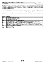
VRVK/6358 Series Vandal Resistant “6 wire Bus” videokit
VRVK/6358 Series - Installation handbook
SPEAK BUSY OPEN
Yellow LED
Red LED
Green LED
4
3
2
1
ON
J1
J2
Art.140
Amplifier for VR4KV Series Videokits
Made in Italy
NONC C PTE SL BS 2 1 +12 +20
J1
J2
P1 = Red / Rosso
P2 = White / Bianco
– ..= Blue / Blu
Reassurance
tone volume
Microphone
volume
Speaker
volume
Setup
Dip-Switch
Connection
terminals
Button Wires
P1=Red
–=Blue
P2=White
Relay
Operating
Mode
LEDS
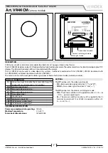
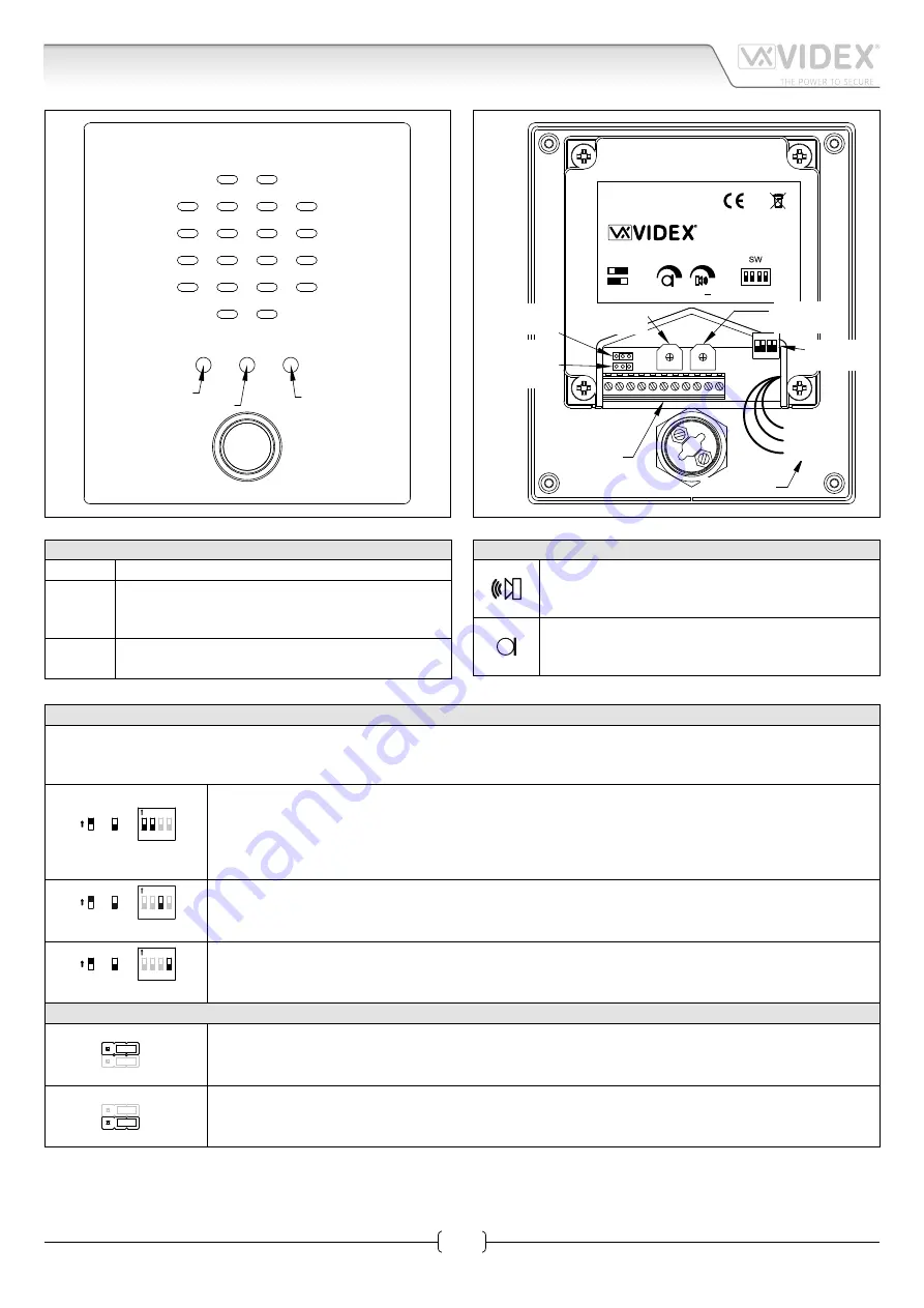
YELLOW Illuminates during the conversation.
RED
Illuminates when the speaker unit is operating or
when other speaker units in the same system are
operating to signal the busy state of the system.
GREEN
Illuminates when the door opens for the duration
of the door opening time.
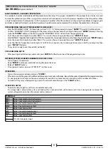
CONTROLS (SPEAKER & MICROPHONE VOLUME)
Trimmer to adjust the speaker volume.
Rotate clockwise to increase or anti-clockwise to de-
crease.
Trimmer to adjust the microphonez volume.
Rotate clockwise to increase or anti-clockwise to de-
crease.
SETTINGS (DIP-SWITCH & JUMPERS)
4 WAY DIP-SWITCH
First two switches are used to set the speaker unit address: the speaker unit address is required for camera recall operation on 2
or more entrance systems.
ON
sw
1 2
3 4
=OFF
=ON
Switches 1,2
Unit Address
OFF OFF 1
ON OFF 2
OFF ON 3
ON ON 4
ON
sw
1 2
3
4
=OFF
=ON
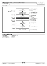
Switch 3
Conversation Time
OFF
60 seconds
ON
120 seconds
ON
sw
1 2 3
4
=OFF
=ON
Switch 4
Door opening time (J2 = “L” position)
OFF
2 seconds
ON
6 seconds
JUMPERS J1, J2
J1
J1 Position
Call tone reassurance volume
Right
High
Left
Low
J1
J2 Position
Door open relay operating mode
Right
Dry contacts
Left
Capacitor discharge
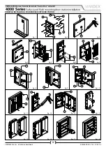
Art. VR4KAMK
Speaker unit

