background image

Bedlift ST327-45R - Service Manual

Page 2

BedLift-ST327-45R_sm_07_Dec2015

 Service: 1-866-821-2647 

 Office: 1-800-210-0141

 www.storevertical.com

SAFETY

Important Safety Instructions

Read this manual carefully to ensure familiarity with the controls and the proper use of the equipment�

The warnings and precautions contained in this manual 

DO NOT

 cover all potential dangers, and hazards 

that may be encountered�

This manual is intended to provide basic safety guidelines for proper operation, maintenance, and servicing 

of the machine�

WARNING – Risk of injury 


- Installation and service of this machine should be performed by qualified service personnel�


- Only properly trained service personnel should have access to the interior components of the 

machine�


- Electrical connections should be performed by qualified electricians�


- Operation must be performed by trained personnel� Never allow children or unauthorized per-

sons to operate the machine�

DANGER – To reduce the risk of electrical shock:


- Keep cord away from heated surfaces or areas where it can be easily damaged�


- Do not change current limit ratings of overload protectors� For further instruction please contact 

our service line�


- Turn all switches to the off position and disconnect power to the machine before cleaning, main-

tenance, or repairs�


- Risk of electrical shock – Connect this machine to a properly  grounded outlet only� See ground-

ing instructions�


- Keep the area of operation clear of all persons and potential hazards�


- Always shut off the main power switch before servicing the machine�


- Keep all guards and shields in place

Use this machine only for its intended purpose as described by these instructions�

Do not use attachments not recommended or approved by the manufacturer�

Never operate this machine if it has been damaged, has a damaged electrical cord, or if it is not working 

properly� Keep all guards and shields in place�

Keep area clean and organized during operation�

For further instruction please contact our service line.

Summary of Contents for BEDLIFT ST327-45R

Page 1: ...BEDLIFT ST327 45R Service Manual...

Page 2: ...atform Bridge Plate 12 Extended Ramps 13 COMPONENTS 14 Machine Overview 14 Rear Main Tubes Bottom 15 Rear Main Tubes Top 16 Front Main Tubes 17 Support Side Tubes 18 Drive System 19 Rear Shaft Chains...

Page 3: ...0141 www storevertical com TABLE OF CONTENTS Bedlift ST327 45R Service Manual WIRING SCHEMATIC 40 MAINTENANCE Maintenance Schedule 44 Preventative Maintenance Checklist 45 DOCUMENT LIST 46 RECOMMENDED...

Page 4: ...d parts ordering Serial No _________________________________________________________________________________ IMPORTANT CAUTION NOTICE Vidir has made every effort to protect operators and others from i...

Page 5: ...nauthorized per sons to operate the machine DANGER To reduce the risk of electrical shock Keep cord away from heated surfaces or areas where it can be easily damaged Do not change current limit rating...

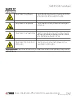
Page 6: ...ard Entanglement loose clothing or jewelry could become entangled or drawn in Safety Hazard Crushing Rolling platform may present a hazard of crushing hospital bed may present hazard of rolling over t...

Page 7: ...s Power supply cord must NOT run through walls ceilings floors and simi lar openings in the building structure Be sure to take measures to prevent physical damage to the power supply cord This include...

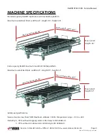
Page 8: ...6 Extra capacity Bedlift maximum load limit 900lbs platform Maximum overall bed limits width 44 5 length 95 height 32 Max overall width 44 5 Max overall width 44 5 Max overall length 95 Max overall le...

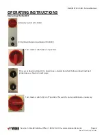
Page 9: ...210 0141 www storevertical com Turn master switch A to on position Press up or down buttons C to lower raise a loaded bed shelf Follow unload load bed procedures as shown on next page Turn master swit...

Page 10: ...Office 1 800 210 0141 www storevertical com OPERATING INSTRUCTIONS Loading the Bedlift 1 Install Bedlift loading ramps and align bed wheels to loading ramps The bottom platform has integrated ramps an...

Page 11: ...dlift ST327 45R Service Manual Page 8 BedLift ST327 45R_sm_07_Dec2015 Service 1 866 821 2647 Office 1 800 210 0141 www storevertical com OPERATING INSTRUCTIONS 3 Remove loading ramps Insert wheel stop...

Page 12: ...327 45R Master Manual OPERATING INSTRUCTIONS 4 Press UP button to raise platform 5 Load the next bed insert wheel stop and repeat until all platforms and ground level hold a bed 6 The bottom bed is st...

Page 13: ...are no other obstructions 2 Press and hold the DOWN button and all platforms will lower and stop once the bottom platform has reached ground level 3 Remove the bottom platform wheel stops and unload t...

Page 14: ...sensor wheel shown in purple Once the gate has passed over the sensor wheel the Bedlift will not operate Pull the gate to the floor Lock the gate with supplied key turning counterclockwise as indicat...

Page 15: ...dge plates eliminate the gap between platform surfaces to accommodate hospital beds with a narrower track the spacing between the 2 front wheels Three bridge plates per platform are required except fo...

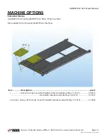
Page 16: ...ded Ramps Available for front loading Bedlift ST3xx ST4xx ST5xx machines Not available for front loading Bedlift ST2xx machines Item Description part 1 Ramp front lip mount for Bedlift manufactured be...

Page 17: ...5R_sm_07_Dec2015 Service 1 866 821 2647 Office 1 800 210 0141 www storevertical com COMPONENTS Machine Overview 1 Drive system Page 19 2 Rear shaft load chains drive chain tensioners Page 20 3 Control...

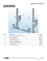
Page 18: ...tem Description part 1 3 8 X 1 1 2 hex bolt full thread gr5 unc 001 0342 2 Ring snap ext 1 2 cs50 116 0004 3 Sprocket idler h40a18 120 0039 4 1 2 Flange nut gr5 unc 004 0017 5 1 2 X 1 1 2 crg bolt f T...

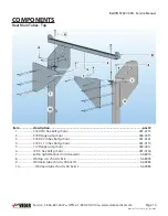
Page 19: ...art 1 3 8 X 3 4 hex bolt gr5 unc 001 0113 2 3 8 Flange nut gr5 unc 004 0015 3 3 8 X 2 3 4 hex bolt gr5 unc 001 0121 4 3 8 X 1 1 4 hex bolt gr5 unc 001 0115 5 1 2 Flange nut gr5 unc 004 0017 6 2 X 3 he...

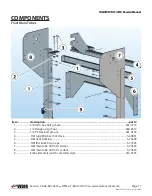
Page 20: ...Front Main Tubes Item description part 1 3 8 X 3 4 hex bolt gr5 unc 001 0113 2 1 2 Flange nut gr5 unc 004 0017 3 1 2 X 3 hex bolt gr5 unc 001 0150 4 Hbl top 80 gbox mnt cface 5 69991 5 Hbl door backi...

Page 21: ...COMPONENTS Support Side Tubes Item Description Part 1 3 8 Flange nut gr5 unc 004 0015 2 3 8 X 2 1 4 hex bolt gr5 unc 001 0257 3 3 8 X 1 3 4 hex bolt gr5 unc 001 0117 4 Hbl btm side support chn drv 5 6...

Page 22: ...r60 56c 107 0046 Flange for gearbox 80R60 56c not shown 107 0048 4 Link connecting 60 105 0037 5 Chain hbl front to back 60 chain drive 5 68956 6 Chain hbl drive 60 chain drive c face 5 69995 7 Key 5...

Page 23: ...ft 5 68947 5 Guard 5 70035 6 Chain 5 69996 7 1 2 X 1 1 2 hex bolt gr5 unc 001 0146 8 1 2 Flange nut gr5 unc 004 0017 9 207 106 Flange 4bolt asm 006 0038 10 1 2 X 1 1 2 crg bolt f T Gr5 unc 001 0069 11...

Page 24: ...rt 1 4 mm hex 004 0037 2 Bolt 4mm x 20mm 001 0005 3 Washer star m4 003 0093 4 Screw combination 1 4 x 1 2 002 0068 5 Bracket 5 67460 6 Mid limit switch 410 0155 7 Contact block norm closed 410 0061 8...

Page 25: ...COMPONENTS Item Description part 1 Top platform 3bed 5 72037 2 Platform backstop lev3 5 68993 3 Wheel mini stop 5 69051 4 Extra vert guard 5 72580 5 Platform hanger tube 5 72041 Bottom Platform Top P...

Page 26: ...ex bolt gr5 unc 001 0150 8 Nut lock 7 16 steel l9 unc 004 0088 9 Carousel chain bolt 2 47290 10 Washer sae 7 16 15 32 x 59 64 x 1 16 003 0125 11 Bushing crsl hook 007 0062 12 1 2 Nylon lock nut gr5 un...

Page 27: ...866 821 2647 Office 1 800 210 0141 www storevertical com COMPONENTS Bottom Platform Detail Item Description part 1 3 8 X 1 HEX BOLT GR5 UNC 001 0114 2 3 8 X 2 HEX BOLT GR5 UNC 001 0119 3 1 4 X 1 HEX B...

Page 28: ...anual Page 25 BedLift ST327 45R_sm_07_Dec2015 Service 1 866 821 2647 Office 1 800 210 0141 www storevertical com COMPONENTS Chain Guard Item Description part 1 Screw d t hwh 1 4 x 1 002 0019 2 Hbl frn...

Page 29: ...al com COMPONENTS Load Chain Guards Item Description part 1 HBL CHN INSIDE WELD LT 3B 5 70035 2 HBL CHN INSIDE WELD RT 3B 5 70031 3 1 4 X 3 4 HEX BOLT GR5 UNC 001 0086 4 HBL PLASTIC CHAIN 5 70165 5 HB...

Page 30: ...l com COMPONENTS Bottom Side Bed Guides Bed Detection Sensors Item Description part 1 Washer sae 3 8 406X 813X 080 003 0008 2 3 8 X 3 4 hex bolt gr5 unc 001 0113 3 Hbl btm side bed guide 5 72568 Item...

Page 31: ...2015 Service 1 866 821 2647 Office 1 800 210 0141 www storevertical com Motor Covers Item Description part 1 Screw combi 1 4 x 3 4 truss head 9 16 dia 002 0120 2 Hbl 3bed frnt cvr btm w dr 5 70544 3 H...

Page 32: ...w storevertical com COMPONENTS Rear Panels optional Item Description part 1 Wshr flat 1 4 003 0114 2 1 4 Flange nut gr5 unc 004 0013 3 1 4 X 3 4 hex bolt gr5 unc 001 0086 4 Screw combi 1 4 x 3 4 truss...

Page 33: ...1 2647 Office 1 800 210 0141 www storevertical com COMPONENTS Side Panels optional Item Description part 1 Hbl side top left 5 70045 2 Hbl side panel mid univ 5 70043 3 Hbl side panel btm right 5 7004...

Page 34: ...Shutter optional Item Description part 1 Hbl front ebox 5 70508 2 Screw combination 1 4 x 1 2 002 0068 3 Hbl ebox side cover 5 70548 4 1 4 Flange nut gr5 unc 004 0013 5 1 4 X 1 1 2 hex bolt gr5 unc 00...

Page 35: ...r sensor wheel 5 73991 2 Wheel hbl door sensor lrg 5 73990 3 Door sensor brkt 5 73859 4 Plate hbl door switch large whl 5 73869 5 Limit switch 5 77705 6 5 16 X 1 hex bolt gr5 unc 001 0100 7 5 16 Flang...

Page 36: ...ter disconnect switch to the on position Press and hold the up button until all platforms have reached the top limit and stop 2 Measure the distance between the top and second platform Measure the dis...

Page 37: ...ers of the top platform All 4 corners must be identical Use adjustment nuts on connector tubes as necessary 4 Press and hold the down button and lower the top platform approx 12 approx 30cm 4 Press an...

Page 38: ...ire white 401 0081 3 Relay ice cube ly2 24vdc 409 0021 4 Relay base ice cube 409 0022 1 Drive ac 2hp 220v 1ph 403 0016 2 Terminal strip 12 wire white 401 0081 1 Drive ac 1hp 220v 1ph 403 0015 2 Termin...

Page 39: ...Bedlift3 plug in using 120VAC 15A 5 75475 Bedlift4 Bedlift5 plug in using 240VAC 15A 5 75476 Bedlift4 Bedlift5 plug in using 240VAC 10A 5 75477 Bedlift4 Bedlift5 Plug Assembly European 120 Volt 50 60...

Page 40: ...1 www storevertical com COMPONENTS Electrical Item Description part Relay ice cube ly2 24vdc 409 0021 Relay base ice cube 409 0022 Item description part Sensor photoelectric 410 0111 Bracket hbl bed s...

Page 41: ...anual Page 38 BedLift ST327 45R_sm_07_Dec2015 Service 1 866 821 2647 Office 1 800 210 0141 www storevertical com COMPONENTS VFD Electrical Connections Ice Cube Relay Bus Strip Connections Numbers Indi...

Page 42: ...Bedlift ST327 45R Service Manual Page 39 BedLift ST327 45R_sm_07_Dec2015 Service 1 866 821 2647 Office 1 800 210 0141 www storevertical com COMPONENTS Control Panel Electrical Connections...

Page 43: ...Bedlift ST327 45R Service Manual Page 40 BedLift ST327 45R_sm_07_Dec2015 Service 1 866 821 2647 Office 1 800 210 0141 www storevertical com WIRING SCHEMATIC...

Page 44: ...T2 T3 T1 T4 T5 T6 T8 T9 T7 R D Y ENT ESC ALTIVAR 31 R1A R1C LI2 LI1 LI3 R2A R2C 24 COM W T3 GND V T2 GND U T1 BRN DOWN BOTTOM LIMIT SWITCH ROLLER ACTUATOR 410 0155 BLU BLK BK WH BRN UP TOP LIMIT SWITC...

Page 45: ...MIT SWITCH ROLLER ACTUATOR 410 0155 BLU BLK BK WH BRN BLU UP TOP LIMIT SWITCH ROLLER ACTUATOR 410 0155 BLK BK WH BRN MID LIMIT SWITCH ROLLER ACTUATOR 410 0155 BLU BLK BK WH 3 4 1 2 ZB4BZ009 Mounting C...

Page 46: ...9 T7 BRN DOWN BOTTOM LIMIT SWITCH ROLLER ACTUATOR 410 0155 BLU BLK BK WH BRN UP TOP LIMIT SWITCH ROLLER ACTUATOR 410 0155 BLU BLK BK WH BRN MID LIMIT SWITCH ROLLER ACTUATOR 410 0155 BLU BLK BK WH 3 4...

Page 47: ...ntenance Unload all platforms and inspect entire machine including the platforms and backstops Inspect upper and lower master links on all 4 load chains Run all platforms up and note bottom platform s...

Page 48: ...s are tight and sprockets have not moved Check limit switches for good condition and proper cut off when operating up down Load Chain Bearings Sprockets and Platforms Remove all beds keep platforms do...

Page 49: ...t ST3xxx_im_08_Dec2015 pdf Bedlift ST4xx 5xx 45R im 07_Dec2015 pdf Bedlift ST327 330 96S im 04_Dec2015 pdf Bedlift ST427 96S im 04_Dec2015 pdf Operator s Manual Bedlift R om 06 June2015 pdf Bedlift S_...

Page 50: ...E 2 Schneider Electric ZB4BZ009 410 0054 PUSHBUTTON TELEMECA NIQUEZB4BA0 2 Schneider Electric ZB4BA0 410 0155 SWITCH ROLLER ACTUA TOR 3 4 Schneider Electric XCMN2115L1 410 0111 SENSOR PHOTOELECTRIC 1...

Page 51: ...1 4 120 0197 2 Chain hbl drive 60 chain drive c face 5 68956 2 Chain hbl front to back 60 chain drive 5 69995 10 Link connecting 60 105 0037 1 Sprocket 60b30 1 3 8 120 0191 4 Chain hbl 3bed load 40 5...

Page 52: ...l assembly 95 lbs ST527 45R 160 x 48 x 28 2200lb 5bedlift standard side panel assembly 275 lbs 5bedlift standard back panel assembly 122 lbs ST233 45X 104 x 48 x 24 1400lbs 2bedlift left side panel as...

Page 53: ...he defect 7 The Buyer is expected to provide access to all equipment covered by this warranty Vidir shall not be responsible for any expense incurred in removing replacing or refinishing any part of t...

Reviews: