background image

9 of 12

Viega Nonprogrammable Thermostat User Guide

UG-HC 566439 1219 Nonprogrammable Thermostat

System Operation 

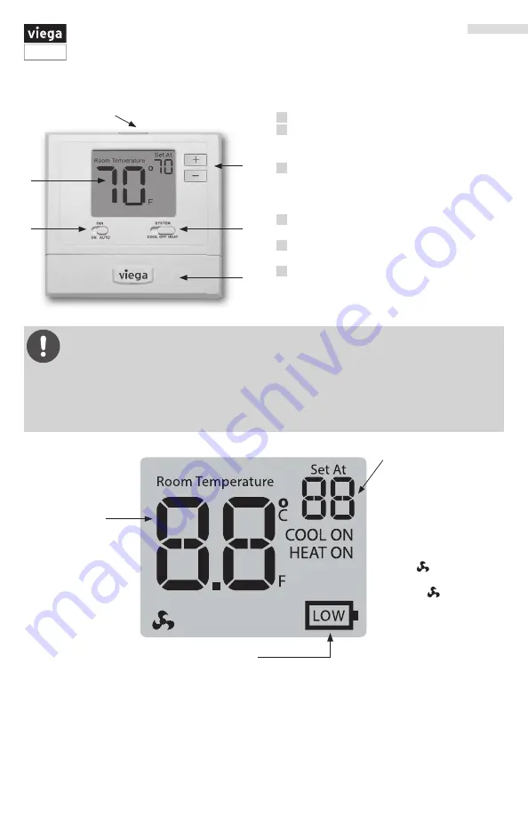
Indicators:

The COOL ON, HEAT 

ON or   icon will 

display when the COOL, 

HEAT or   (fan) is on.

The compressor delay 

feature is active if these 

icons are flashing. The 

compressor will not turn 

on until the 5 minute 

delay has elapsed.

Important:

The low battery indicator is displayed when the AA battery power is low. If the user fails 

to replace the battery within 21 days, the screen will only show the low battery indicator 

but maintain all functionality. If the user fails to replace the batteries after an additional 21 days 

(days 22-42 since first “low battery” display) the set points will change to 55°F (Heating) and 85°F 

(Cooling). If the user adjusts these setpoints away from these it will hold for 4 hours then return to 

either 55°F or 85°F. After day 63 the batteries must be replaced immediately to avoid freezing or 

overheating because the thermostat will shut the unit off until the battery is changed.

Thermostat Display

Indicates the current 

room temperature.

Displays the user 

selectable setpoint 

temperature.

Low Battery Indicator:

Replace batteries when this 

indicator is shown.

1

  LCD Display

2

  Glow in the dark light button


Push the glow in the dark button and 

screen will illuminate. 

3

  Fan switch


Set to AUTO to run the fan anytime heating 

or cooling is running.


Set to ON to run the fan at all times.

4

  System switch


Set to heating / cooling or off.

5

  Easy change battery door


2 AA batteries included

6

  Temperature setpoint buttons


Use the + or - buttons to adjust the room 

temperature.

1

6

2

3

4

5

Summary of Contents for 15116

Page 1: ...the location should be representative of the building Installation Tips Applications Guide The Programmable Heat Cool Thermostat can be use for the following applications Gas or Oil Heat Electric Furnace Heat Pump No Aux or Emergency Heat Heat Only Systems Cool Only Systems The following applications are not recommended Heat Pump with Aux or Emergency Heat Multi stage Systems Wall Locations The th...

Page 2: ...se Attaching the Thermostat to the Subbase Align the 4 tabs on the subbase with corresponding slots on the back of the thermostat then push gently until the thermostat snaps in place To insure a solid fit between the thermostat and the subbase Mount subbase to a flat wall or electrical box Use screws provided Drywall anchors should be flush with the wall Wires should be pushed into the wall A trai...

Page 3: ...ne batteries included High quality alkaline batteries are recommended Simple operating instructions are found on the back of the battery door Important High quality alkaline batteries are recommended Rechargeable batteries or low quality batteries do not guarantee a 1 year life span Thermostat Settings Gas or Electric Setup Gas For systems that control the fan during a call for heat put the fan op...

Page 4: ... Heat pump changeover valve energized in cooling RC Transformer power for cooling RH Transformer power for heating B Heat pump changeover valve energized in heating C Common wire from secondary side of cooling system transformer Viega Thermostat Terminal Conversion C W C W E L N R C W RH RC RH RC Thermostats 15116 15117 Thermostat 15118 Zone Controls 18060 18062 Digital Thermostat 18050 Zone Contr...

Page 5: ...o connect W and Y terminals Set fan operation setting to Electric Optional 24 VAC common connection when thermostat is used in battery power mode 3 3 8 3 3 3 3 8 3 3 3 3 8 3 3 8 3 3 3 8 3 3 3 3 8 0 Typical 1H 1C System 2 Transformer Typical Heat Only System With Fan Typical Cool Only System Compressor Relay Heat Relay Fan Relay HOT Compressor Relay Heat Relay Remove Jumper Fan Relay HOT HOT HOT HO...

Page 6: ...3FE Viega Legend Thermostat Low Voltage Line Voltage Part Numbers 15116 15117 and 15118 Connect the RC terminal from the thermostat to R terminal on the zone control Connect the W terminal from the thermostat to W terminal on the zone control for part number 15118 connect W E terminal from the thermostat to W terminal on the zone control Connect the C terminal from the thermostat to the C terminal...

Page 7: ...minal on the zone control for part number 15118 connect W E terminal from the thermostat to W terminal on the zone control Connect the C terminal from the thermostat to the C terminal on the zone control Viega Viega 0 0 8 3 8 3 8 3 8 3 N 3 3 8 5 3 3 0 8 8 3 3 0 8 3 3 0 8 MBDL 8IJUF FMMPX FMMPX 3FE 3FE FMMPX FMMPX 3FE 3FE Viega Viega Powerhead 15061 15070 2 Wire 24 V For use with Stainless Manifold...

Page 8: ... Thermostats to 2 Wire Powerheads Connecting Viega Thermostats to 4 Wire Powerheads 4 powerheads may be connected to each thermostat 4 powerheads may be connected to each thermostat C O B W E RH G Y Thermostat 15118 W2 Y2 RC Class II Transformer C R 120 V AC Power Supply N L Red Red Yellow Yellow Viega To T T boiler contact pump replay or other auxiliary device requiring contact closure Legend The...

Page 9: ...to 55 F Heating and 85 F Cooling If the user adjusts these setpoints away from these it will hold for 4 hours then return to either 55 F or 85 F After day 63 the batteries must be replaced immediately to avoid freezing or overheating because the thermostat will shut the unit off until the battery is changed Thermostat Display Indicates the current room temperature Displays the user selectable setp...

Page 10: ...e thermostat reads 70 and you would like it to read 72 then select 2 You can adjust the room temperature display to read 4 F to 4 F above or below the factory calibrated reading 0 F Compressor Short Cycle Delay The compressor short cycle delay protects the compressor from short cycling This feature will not allow the compressor to be turned on for 5 minutes after it was last turned off Selecting O...

Page 11: ... setpoint and turn the cooling off at approximately 0 5 F Below the setpoint 0 5 Heating Swing The swing setting often called cycle rate differential or anticipation is adjustable A smaller swing setting will cause more frequent cycles and a larger swing setting will cause fewer cycles The heating swing setting is adjustable from 0 2 F to 2 F For example A swing setting of 0 5 F will turn the heat...

Page 12: ...t Adjusting the Room Temperature The current room temperature is displayed in large text in the center of the thermostat under the room temperature heading The set point or desired room temperature is in the upper right corner of the display under set at To raise or lower the desired set at temperature use the red and blue and buttons on the top right of the thermostat ...

Reviews: