5 of 20
Viega Multifunctional Thermostat User Guide
UG-HC 566441 1219 Multifunctional Thermostat (EN)
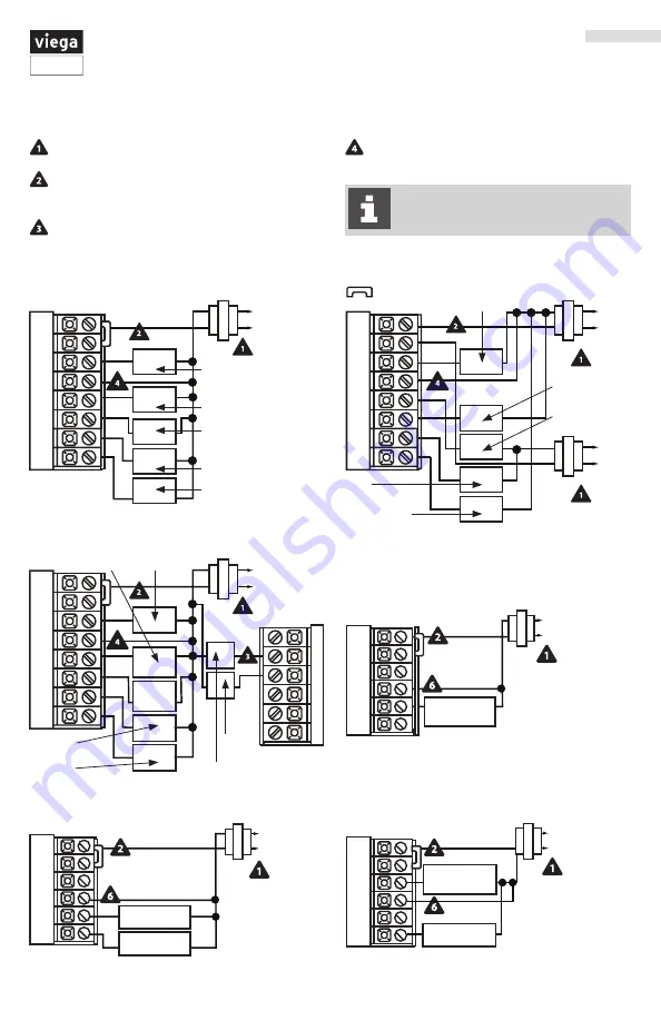
In many heat pump systems with no
emergency heat relay a jumper can be
installed between E and W2.
Typical Industry Wiring Diagrams
Power supply
Factory-installed jumper. Remove only
when installing on 2-transformer systems
Use either O or B terminals for changeover
valve
Optional 24 VAC common connection when
thermostat is used in battery power mode
3$
3)
:
$
8&
(
$
3
-
-
3$
3)
$
3
-
-
:
$
8&
(
3$
3)
:
$
8&
(
8
:
3$
3)
O
B
$
3
-
-
:
$
8&
(
8
:
3$
3)
$
3
-
-
:
$
8&
(
8
:
3$
3)
$
3
-
-
$
3
-
-
$
3
-
-
3$
3)
:
$
8
(
Typical 2H/2C System: 1 Transformer
Typical 2H/2C System: 2 Transformers
Typical 3H/2C Heat Pump System
Typical Heat Only System with Fan
Typical Cool-Only System
Typical Heat Only System with Fan
(HOT)
(HOT)
(HOT)
(HOT)
Fan Relay
Compressor
Relay
Heat
Relay
Compressor
Relay 2
Auxillary
Heat
Change Over Valve
Cool Change Over Valve
Fan Relay
Heat Relay
(HOT)
Compressor
Relay
Compressor
Relay
Compressor
Relay
Compressor
Relay 2
Compressor
Relay 2
Heat
Relay
HeatRelay
Heat
Relay 2
Heat
Relay 2
Emergency
Heat Relay
Fan
Relay
Fan
Relay
Fan Relay
(HOT)
(HOT)
Remove
Jumper


