F-27027-5
©
Copyright 2010 Schneider Electric All Rights Reserved.
5
INSTALLATION
Inspection
Inspect the package for damage. If damaged, notify the appropriate carrier immediately.
If undamaged, open the package and inspect the device for obvious damage.
Return damaged products.
Requirements
•
Tools (not provided)
— Writer’s Note: Need list.
•
Training: Installer must be a qualified, experienced technician
•
Other accessories as appropriate
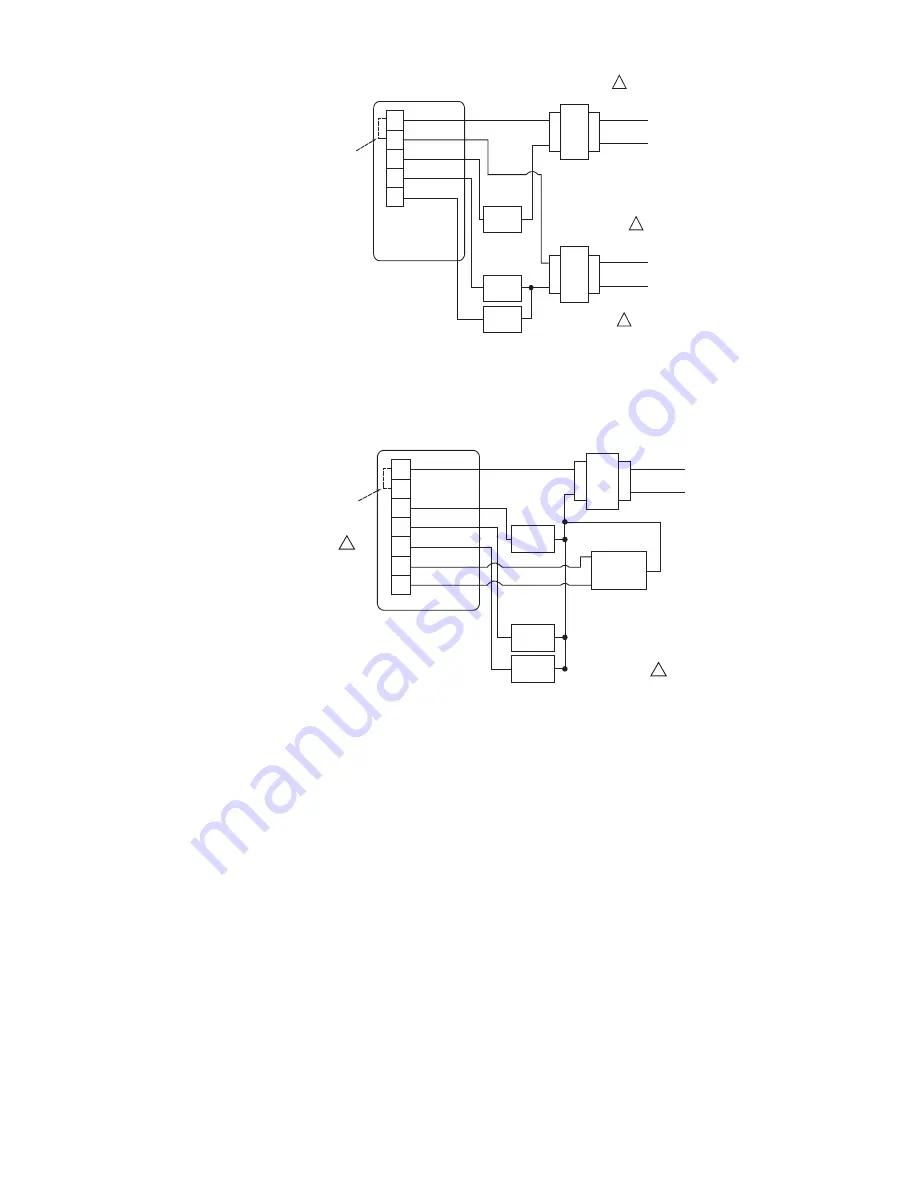
24 VAC HEATING
TRANSFORMER
24 VAC
120 VAC
24 VAC COOLING
TRANSFORMER
120 VAC
FAN
RELAY
COOLING
RELAY
RC
RH
Y
W
G
HEATING
RELAY
1
1
1
If one of the secondary sides
of both transformers are grounded,
grounded sides must be connected
together.
FACTORY
INSTALLED
JUMPER
Figure-5 Typical T205 Wiring to Heating/Cooling System With Dual Transformer.
24 VAC HEATING
TRANSFORMER
24 VAC
120 VAC
FAN
RELAY
COOLING
RELAY
RC
RH
Y
W
G
B
O
HEATING
RELAY
REVERSING
VALVE
1
1
Either the B or O output
will be connected to the
reversing valve. Terminal
O supplies 24V on a call
for cooling. Terminal B
supplies 24V on a call for
heat.
FACTORY
INSTALLED
JUMPER
Figure-6 Typical T207 Wiring To Heating/Cooling System With Single
Transformer & Reversing Valve.


