background image

5

VIEGA      1-800-976-9819 

PI-16015-03/09

2   Control operation

2.1  General operation

When the Basic Heating Control is 
powered up, the control displays the 
control type number in the LCD for 2 
seconds. Next, the software version 


is displayed for 2 seconds. Finally, 


the control enters into the normal 
operating mode.

The Basic Heating Control uses a 

floating action mixing or injection valve 

to vary the supply water temperature  
to a hydronic system. The supply  

water temperature is based on 


the outdoor temperature.

The maximum water temperature 
setting in the Basic Heating Control 

should not be used as a safety high 

limit control. To protect floors from 
high water temperatures in case of 

main control failure or removal, use a 
Viega Modulating Safety High Limit 
Control (stock code 16116) on the 
outlet injection valve of the 
Injection Station.

2.2  Control Features

2.2.1   outdoor Reset

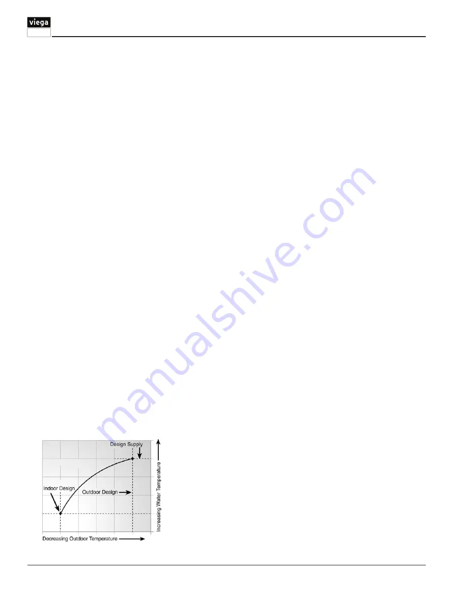
The Basic Heating Control calculates 
a mixing supply water temperature 

based on the outdoor air temperature. 

The Basic Heating Control uses a 
heating curve and optional indoor 

temperature feedback from an indoor 

sensor in this calculation.

2.2.2   Floating action

A 24 V (AC) floating action actuator 

motor is connected directly to 
the Basic Heating Control on the 

Com, Opn and Cls terminals (7, 8, 

and 9). The Basic Heating Control 
pulses the actuator motor open 
or closed to maintain the correct 
mixed supply water temperature at 
the supply sensor. The valve that 
the actuator is connected to can 

be either an injection valve (on the 
Injection Station), a mixing valve, or 

a diverting valve. A visual indication 
as to whether the control is currently 
opening or closing the mixing valve 
is displayed in the LCD.

2.2.3   Warm Weather shut Down

The Basic Heating Control monitors 
the outdoor temperature and shuts 
off the heating system seasonally 
when outdoor temperatures exceed 

the WWSD setting. This reduces 

energy use during the summer 
when the heating system is not 
needed and saves wear on system 
components.  To prevent the system 
from seizing due to long periods of 

no use, the circulator, actuator, and 

valve are exercised periodically (see 

below).

2.2.4   Exercising  

The Basic Heating Control has a 

built-in exercising function. If the 

system pump or valve has not 

been operated at least once every 
3 days, the control turns on the 
output for a minimum of 10 seconds. 
This minimizes the possibility of 

a circulator pump or valve seizing 
during a long period of inactivity. 
The Basic Heating Control ensures 
that the mixing valve operates over 
its entire range at least once each 

exercising period. While the control 
is exercising, the Test LED flashes. 

Note: The exercising function does 

not work if power to the control, 
circulator, or valve is disconnected.

ContRoL oPERAtIon - CHAPtER 2

Summary of Contents for Basic Heating Control

Page 1: ...Radiant Basic Heating Control Installation Manual March 2009...

Page 2: ...he supply water temperature The control has a Liquid Crystal Display LCD to view system status and operating information Additional functions include User comfort adjustment to increase or decrease bu...

Page 3: ...use the LCD display Control Sections 3 and 4 which discusses how the mixing device and boiler are controlled Installation Section 5 which details the mounting and connection process for the control a...

Page 4: ...in operation Burner Displays when the boiler relay is turned on F C Displays the units of measurement that all of the temperatures are to be displayed in the control Pointer Displays the actuator oper...

Page 5: ...d 9 The Basic Heating Control pulses the actuator motor open or closed to maintain the correct mixed supply water temperature at the supply sensor The valve that the actuator is connected to can be ei...

Page 6: ...r where the building is located This temperature is used when performing the heat loss calculations for the building If a cold outdoor design temperature is selected the mixing supply temperature rise...

Page 7: ...ion of the mixing valve exceeds 30 The boiler contact remains closed until the position of the mixing valve reduces below 15 This setting would normally be chosen for low mass boilers copper fin tube...

Page 8: ...n wiring hardware and conduit fittings Before removing the knockouts check the wiring diagram and select those sections of the chamber with common voltages Do not allow the wiring to cross between sec...

Page 9: ...s can be run in a grounded metal conduit If using shielded cable the shield wire should be connected to the COM sensor terminal on the control and not to earth ground Replace the front cover of the se...

Page 10: ...ircuit to the neutral N terminal 4 Valve Actuator Terminals 7 8 and 9 are powered with 24 VAC from the control There is no need to provide a separate 24 VAC power source for the valve actuator R Opn 7...

Page 11: ...o be tested and the readings compared Test the sensors according to the instructions on page 15 Test the Power Supply Make sure exposed wires and bare terminals are not in contact with other wires or...

Page 12: ...iring until the boiler pump is running If the boiler operates properly disconnect the power and remove the jumper Connecting the Control Make sure all power to the devices and terminal blocks is off a...

Page 13: ...n the User Interface see Display Settings below Boiler Enable 30 Boiler Enable 10 The position of this switch determines at which valve position the control will close the Boiler contact under normal...

Page 14: ...e 16108 on the Injection Station to protect control in case of main control failure or removal Set higher than MIX DSGN and account for the heat loss of distribution piping WWSD Warm Weather Shut Down...

Page 15: ...1k 1000 is required to measure the sensor resistance In addition to this the actual temperature must be measured with a good quality digital thermometer If a thermometer is not available a second sen...

Page 16: ...which devices should be operating as indicated by the LCD This information is an essential step if additional assistance is required to diagnose the problem Isolate the problem between the control and...

Page 17: ...control will operate the mixing valve at a fixed output Locate the problem as described in Section 5 7 To clear the error message from the control after the sensor has been repaired press the Item but...

Page 18: ...18 VIEGA 1 800 976 9819 PI 16015 03 09 MECHANICAL AND ELECTRICAL DIAGRAMS CHAPTER 7 Pump Pump Pump Pump...

Page 19: ...03 09 MECHANICAL AND ELECTRICAL DIAGRAMS CHAPTER 7 Three Position Actuator White wire common green wire open brown wire close Mixing Valve Actuator Blue wire common brown wire clockwise rotation black...

Page 20: ...Dimensions 6 5 8 H x 7 9 16 W x 2 13 16 D 170 x 193 x 72 mm Approvals CSA C US meets ICES FCC regulations for EMI RFI Ambient Conditions Indoor use only 32 to 102 F 0 to 39 C 90 RH non condensing Powe...

Page 21: ...21 VIEGA 1 800 976 9819 PI 16015 03 09 NOTES...

Page 22: ...22 VIEGA 1 800 976 9819 PI 16015 03 09 NOTES...

Page 23: ...23 VIEGA 1 800 976 9819 PI 16015 03 09 NOTES...

Page 24: ...industry Viega 301 N Main Wichita KS 67202 Phone 1 877 843 4262 1 800 976 9819 Fax 1 800 976 9817 www viega com PI IM 16016 03 09 ProPress System Flameless copper press technology ProPress System Fla...

Page 25: ...trol of Viega Mixing Stations Enhanced Mixing Stations and diverting valves The actuator is used in electronic temperature control systems which use hot and or cold water as the controlled medium in r...

Page 26: ...tion of a screw spindle which is driven in both directions by a synchronous motor through a set of gears A magnetic coupling limits the torque of the gear assembly and the driving force of the actuato...

Page 27: ...optional circulator activation function and built in transformer Features LED indicator lights 4 or 6 Zone Control options Simplified wiring Built in transformer Specifications Control Input Control...

Page 28: ...minal of the Zone Control Connect a jumper from the R1 terminal to 3 R2 terminal of the Zone Control See diagram to right Priority Operation Switching the DIP switch to Priority ON will cause all othe...

Page 29: ...field selectable differential The cool output differential is fixed at 2F degrees The setpoint is displayed and changed by pressing one of the setpoint buttons up or down Installation is simplified b...

Page 30: ...25 F 5 to 53 C Humidity 95 non condensing Shipping Weight 0 4 lbs 170 g Location NEMA Type 1 a On T20X FP freeze protection models a relay will provide power to a valve or relay if the thermostat fail...

Page 31: ...functional in heat only models Table 2 Field Selectable Jumper Options Feature Jumpered Not Jumpered 1 Display Celsius Fahrenheit 2 Heating operation differential 2 degrees 1 degree 3 Heat control No...

Page 32: ...0 VAC FAN RELAY COOLING RELAY RC Y G Optional 250 Ohm 5 watt resistor is needed only if power drops below 75 milliamps 1 1 1 Figure 3 Typical T204 Wiring to Cooling System With Single Transformer 24 V...

Page 33: ...G TRANSFORMER 120 VAC FAN RELAY COOLING RELAY RC RH Y W G HEATING RELAY 1 1 1 If one of the secondary sides of both transformers are grounded grounded sides must be connected together FACTORY INSTALLE...

Page 34: ...nd used in accordance with the instructions Even when instructions are fol lowed there is no guarantee that interference will not occur in a particular installation If this equipment causes harmful in...

Page 35: ...COOL OFF system switch and a FAN ON AUTO fan switch Applications include direct expansion cooling only systems Refer to Figure 3 T205 The T205 models are heat cool models with manual changeover The u...

Page 36: ...is below 75 milliamps install a 250 ohm 5 watt resistor in parallel across the switched load Recheck for 75 milliamps The T200 thermostats must have 75 milliamps to function properly 4 Verify system H...

Page 37: ...owerhead with the white cap Three indicator windows allow the position of the valve to be verified valve is open when red bar is visible in window Compact design provides additional clearance for inst...

Reviews: