


Installation
19 of 36
IM-HC 561174 1120 Basic Heating Control
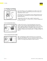
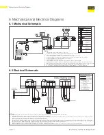
Boiler Contact
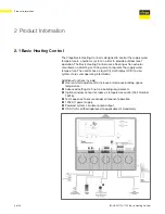
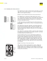
The Boiler terminals (5 and 6) are an isolated (dry) output in the Basic
Heating Control. There is no power available on these terminals from
the control. These terminals are to be used as a switch to either make
or break the boiler circuit. When the Basic Heating Control requires the
boiler to fire, it closes the contact between terminals 5 and 6.
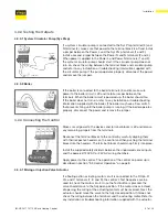
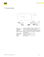
4.2.3 Sensor and Unpowered Input Connections
Do not apply power to these terminals as this will damage the control.
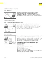
Connect the two wires from the Outdoor Sensor to the Com and Out
terminals (11 and 12). The Outdoor Sensor is used by the Basic Heating
Control to measure the outdoor air temperature.
4.2.3.1 Outdoor Sensor
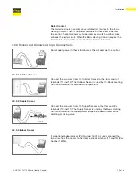
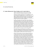
Connect the two wires from the Supply Sensor to the Com and Mix
terminals (10 and 11). The Supply Sensor is used by the Basic Heating
Control to measure the supply water temperature downstream of the
diverting or mixing valve.
4.2.3.2 Supply Sensor
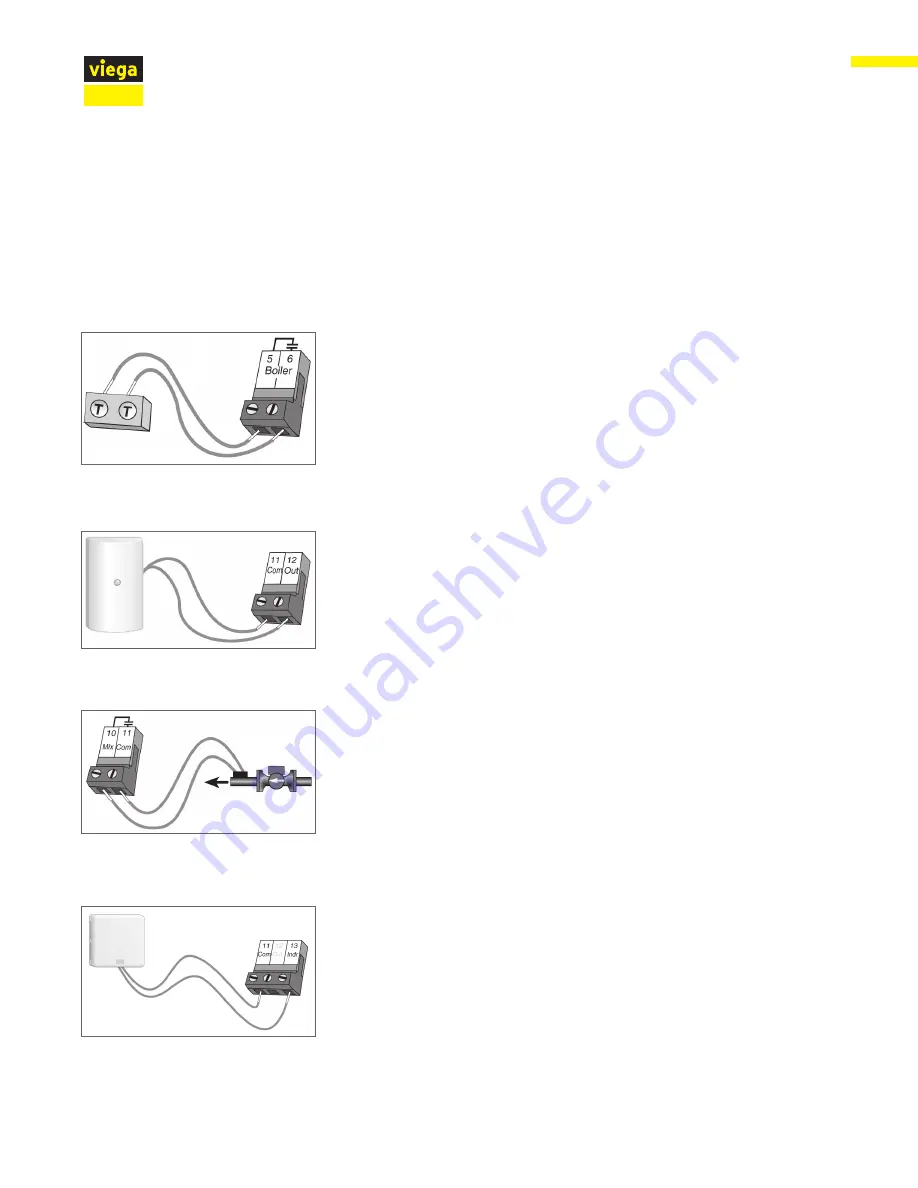
If an optional indoor sensor (Part Number 16016) is used, connect the
two wires from the sensor to the Com and Indr terminals (11 and 13) (Part
Number 16016).
4.2.3.3 Indoor Sensor
System
Pump
Supply
Sensor
Summary of Contents for IM-HC 561174 1120
Page 1: ...Installation Manual Viega Basic Heating Control ...
Page 2: ......


