


Installation
21 of 36
IM-HC 561174 1120 Basic Heating Control
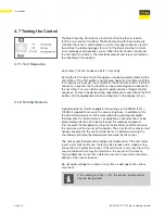
4.3.3 Testing the Outputs
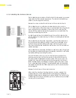
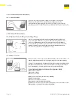
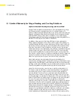
If a system circulator pump is connected to the Sys Pmp terminal (3) and
N terminal (4), make sure that power to the terminal block is off and install
a jumper between the Power L and the Sys Pmp terminals (1 and 3).
Install a second jumper between the Power N and N terminals (2 and 4).
When power is applied to the Power L and Power N terminals (1 and 2),
the system circulator pump should start. If the circulator pump does not
turn on, check the wiring between the terminal block and circulator pump
and refer to any installation or troubleshooting information supplied with
the circulator pump. If the pump operates properly, disconnect the power
and remove the jumpers.
4.3.3.1 System Circulator Pump (Sys Pmp)
System
Pump
120V AC
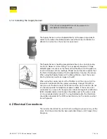
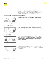
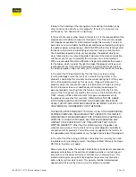
If the boiler is connected to the boiler terminals (5 and 6), make sure
power to the boiler circuit is off and install a jumper between the
terminals. When the boiler circuit is powered up, the boiler should fire.
If the boiler does not turn on, refer to any installation or troubleshooting
information supplied with the boiler. (The boiler may have a flow switch
that prevents firing until the boiler pump is running.) If the boiler operates
properly, disconnect the power and remove the jumper.
4.3.3.2 Boiler
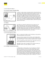
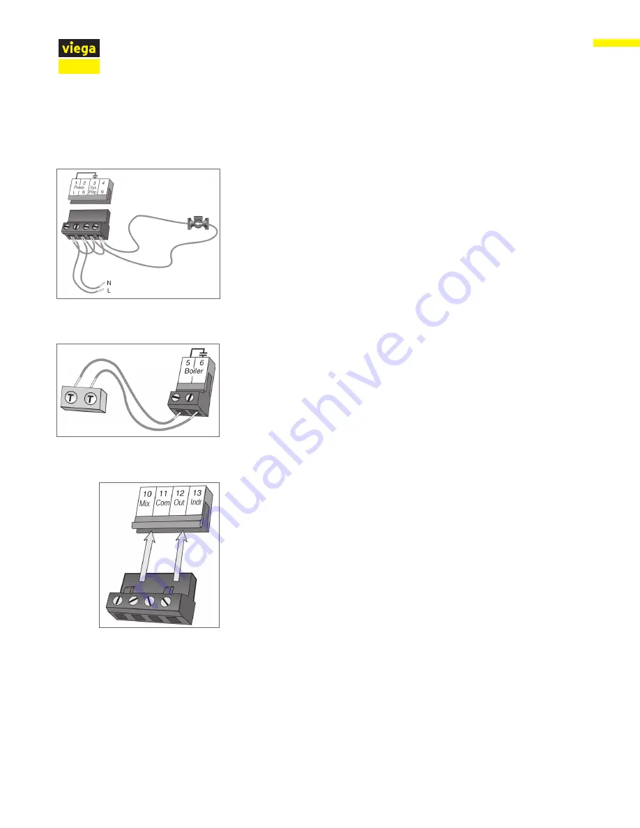
4.3.4 Connecting the Control
Make sure all power to the devices and terminal blocks is off and remove
any remaining jumpers from the terminals.
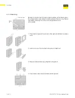
Reconnect the terminal blocks to the control by carefully aligning them
with their respective headers on the control and then pushing the terminal
blocks into the headers. The terminal blocks should snap firmly into place.
Install the supplied safety dividers between the unpowered sensor inputs
and the powered 120V AC or 24V AC wiring chambers.
Apply power to the control. The operation of the control on power up is
described in section "3.3 Control Operation" on page 8.
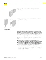
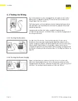
If a floating action actuating motor circuit is connected to the R Opn, R
Cls, and C terminals (7, 8, and 9), the control’s Test Sequence can be
used to check the motor circuit. Once the Test button is pressed, the
valve should move to the fully open position. If the motor closes instead
of opening, the wiring of the actuating motor must be reversed. Next, the
actuator should move the valve to the fully closed position. If it does not,
check the wiring between the terminals and the actuating motor. Refer to
any installation or troubleshooting information supplied with the actuator.
4.3.4.1 Mixing or Injection Valve Actuator
Summary of Contents for IM-HC 561174 1120
Page 1: ...Installation Manual Viega Basic Heating Control ...
Page 2: ......


