Installation
18 of 36
IM-HC 561174 1120 Basic Heating Control
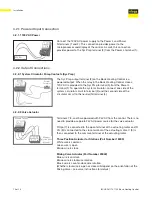
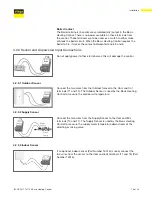
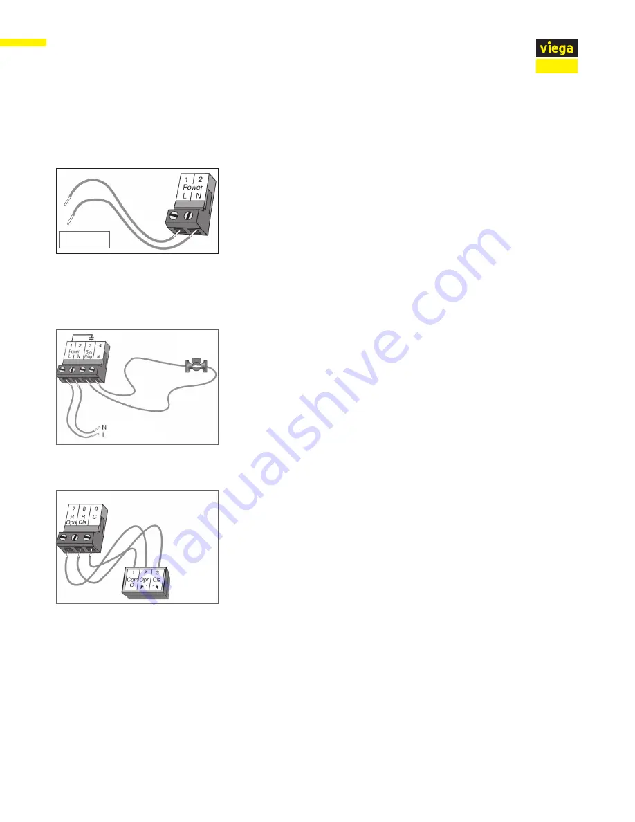
4.2.1 Powered Input Connection
Connect the 120V AC power supply to the Power L and Power
N terminals (1 and 2). This connection provides power to the
microprocessor and display of the control. As well, this connection
provides power to the Sys Pmp terminal (3) from the Power L terminal (1).
4.2.1.1 120V AC Power
120V AC
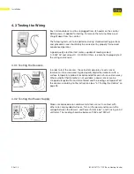
4.2.2 Output Connections
The Sys Pmp output terminal (3) on the Basic Heating Control is a
powered output. When the relay in the Basic Heating Control closes,
120V AC is provided to the Sys Pmp terminal (3) from the Power L
terminal (1). To operate the system circulator, connect one side of the
system circulator circuit to terminal (3) and the second side of the
circulator circuit to the neutral (N) terminal (4).
4.2.2.1 System Circulator Pump Contacts (Sys Pmp)
120V AC
System
Circulator
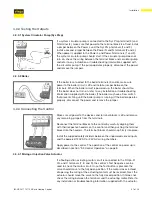
4.2.2.2 Valve Actuator
Terminals 7, 8, and 9 are powered with 24V AC from the control. There is no
need to provide a separate 24V AC power source for the valve actuator.
R Opn (7) is connected to the open terminal of the actuating motor and R
Cls (8) is connected to the close terminal of the actuating motor. C (9) is
then connected to the common terminal of the actuating motor.
Three Position Actuator for Stations (Part Number 18003)
White wire is common
Green wire is open
Brown wire is close
Mixing Valve Actuator (Part Number 20042)
Blue wire is common
Brown wire is clockwise rotation
Black wire is counter-clockwise rotation
(Whether clockwise is open or close will depend on the orientation of the
Mixing Valve – see valve instructions for details)
Powered Output
Mixing or
Injection Valve
Actuator
Summary of Contents for IM-HC 561174 1120
Page 1: ...Installation Manual Viega Basic Heating Control ...
Page 2: ......

