background image

Installation

26 of 36

IM-HC 561174 1120 Basic Heating Control

4.7 Testing the Control

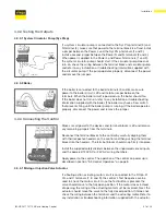
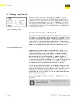
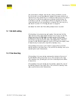
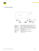
The Basic Heating Control has a built-in test routine that is used to 

test the main control functions. The Basic Heating Control continually 

monitors the sensors and displays an error message whenever a fault is 

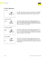
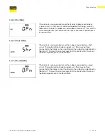
found. See the following pages for a list of the Basic Heating Control’s 

error messages and possible causes. When the Test button is pressed, 

the test light is turned on. The individual outputs and relays are tested in 

the following test sequence.

4.7.1 Test Sequence

Each step in the test sequence lasts 10 seconds.

During the test routine, the test sequence may be paused by pressing the 

Test button. If the Test button is not pressed again for 5 minutes while the 

test sequence is paused, the control exits the entire test routine. If the test 

sequence is paused, the Test button can be pressed again to advance to 

the next step. This can also be used to rapidly advance through the test 

sequence. To reach the desired step, repeatedly press and release the Test 

button until the appropriate device and segment in the display turn on.

4.7.2 Testing Sensors

A good quality test meter capable of measuring up to 5,000kΩ (1kΩ = 

1000Ω) is required to measure the sensor resistance. In addition to this, 

the actual temperature must be measured with a good quality digital 

thermometer. If a thermometer is not available, a second sensor can be 

placed alongside the one to be tested and the readings compared.

First measure the temperature using the thermometer and then measure 

the resistance of the sensor at the control. The wires from the sensor must 

not be connected to the control while the test is performed. Using the 

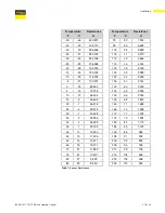
chart below, estimate the temperature measured by the sensor. 

The sensor and thermometer readings should be close. If the test meter 

reads a very high resistance, there may be a broken wire, a poor wiring 

connection, or a defective sensor. If the resistance is very low, the wiring 

may be shorted, there may be moisture in the sensor, or the sensor 

may be defective. To test for a defective sensor, measure the resistance 

directly at the sensor location.

Do not apply voltage to a sensor at any time as damage to the sensor 

may result. 

If the reading is off by +/- 5% the sensor is bad and will 

need to be replaced.

Summary of Contents for IM-HC 561174 1120

Page 1: ...Installation Manual Viega Basic Heating Control ...

Page 2: ......

Page 3: ...___________ 10 3 5 3 Indoor Sensor Optional _ _________________________ 10 3 6 Temperature Control Installer Information_ _________________ 10 3 6 1 Outdoor Design OUTDR DSGN _ __________________ 10 3 6 2 Room Room _ __________________________________ 11 3 6 3 Mix Design MIX DSGN __________________________ 11 3 7 Temperature Control Advanced Information________________ 11 3 7 1 Mixing Indoor MIX I...

Page 4: ..._____ 24 4 6 1 ROOM_ ________________________________________ 24 4 6 2 OUTDR DSGN__________________________________ 24 4 6 3 MIX DSGN_____________________________________ 24 4 6 4 MIX INDR______________________________________ 24 4 6 5 MIX MAX_ ______________________________________ 25 4 6 6 WWSD________________________________________ 25 4 6 7 UNITS_________________________________________ 25 4 7...

Page 5: ...ble damage to property Notes give additional helpful tips 1 1 Disclaimer 1 2 Symbols Used The following symbols may be used within this document Viega products are designed to be installed by licensed and trained plumbing and mechanical professionals who are familiar with Viega products and their installation Installation by non professionals may void Viega LLC s warranty This document is subject ...

Page 6: ...mperature The control has a Liquid Crystal Display LCD to view system status and operating information Additional functions include User comfort adjustment to increase or decrease building space temperature Advanced settings to fine tune building requirements Optional indoor sensor for room air temperature control Part Number 16016 Test sequence to ensure proper component operation 120V AC power s...

Page 7: ... have reached the last available item pressing and releasing the Item button will return the display to the first item To make an adjustment to a setting in the control press and hold simultaneously for one second the Item and buttons The display will then show the word ADJUST in the top right corner Then select the desired item using the Item button Finally use the and or button to make the adjus...

Page 8: ...ntrol displays the control type number in the LCD for two seconds Next the software version is displayed for two seconds Finally the control enters into the normal operating mode The Basic Heating Control uses a floating action that can control Viega diverting or mixing valves to vary the supply water temperature to a hydronic system The supply water temperature is based on the outdoor temperature...

Page 9: ...hether the control is currently opening or closing the mixing valve is displayed in the LCD 3 4 3 Warm Weather Shut Down WWSD The Basic Heating Control monitors the outdoor temperature and shuts off the heating system seasonally when outdoor temperatures exceed the Warm Weather Shut Down setting This reduces energy use during the summer when the heating system is not needed and saves wear on syste...

Page 10: ...eather Shut Down During WWSD the system Circulator is operated periodically based on the Exercise feature 3 6 2 Mixing Target Temperature MIX TARGET The MIX TARGET temperature is calculated from the heating curve settings outdoor air temperature and optionally indoor air temperature The control displays the temperature that it is currently trying to maintain as the mixing supply temperature 3 6 3 ...

Page 11: ...Mixing Indoor MIX INDR The MIX INDR is the room temperature used in the original heat loss calculations for the building This setting establishes the beginning of the Heating Curve for the mixing zones 3 7 2 Mixing Maximum MIX MAX The MIX MAX sets the highest water temperature that the control is allowed to calculate as the MIX TARGET temperature If the control does target the MIX MAX setting and ...

Page 12: ...e boiler contact when the position of the mixing valve exceeds 30 The boiler contact remains closed until the position of the mixing valve reduces below 15 This setting would normally be chosen for low mass boilers copper fin tube etc or systems with low thermal mass in the loop between the boiler and the mixing valve recommended for most Viega applications In the 10 position the Basic Heating Con...

Page 13: ...r CAUTION Improper installation and operation of this control could result in damage to the equipment and possibly even personal injury It is your responsibility to ensure that this control is safely installed according to all applicable codes and standards This electronic control is not intended for use as a primary limit control Other controls that are intended and certified as safety limits mus...

Page 14: ...he control upward The base may then be mounted by screwing it to a wall or mounting board screws not included 1 Press down at grips on top of cover then pull out and down to release cover 2 Loosen screws at front and pull wiring cover straight out 3 Remove safety dividers by pulling them straight out 4 Press release clip on base and slide control upward Mounting holes Release clip ...

Page 15: ... as the wires will interfere with safety dividers that should be installed at a later time Power must not be applied to any of the wires during the rough in wiring stage Install the Outdoor Sensor and Supply Sensor according to the instructions on the next two pages and run the wiring back to the control If an Indoor Sensor optional is used install the sensor according to the instructions included...

Page 16: ...osed to heat sources such as ventilation or window openings The Outdoor Sensor should be installed at an elevation above the ground that will prevent accidental damage or tampering and where it will not be covered by drifting snow during the winter Connect 18 AWG or similar wire to the two terminals provided in the enclosure and run the wires from the sensor to the control Do not run the wires par...

Page 17: ...e sensor into the immersion well see image to the left When using the supply sensor with a ProBloc insert the sensor into the immersion well located in the supply valve body Connect 18 AWG or similar wire to the two wires of the sensor and then to the control Do not run the wires parallel to telephone or power cables If the sensor wires are located in an area with strong sources of electromagnetic...

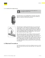
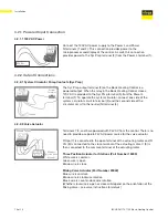
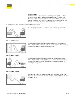
Page 18: ...de of the circulator circuit to the neutral N terminal 4 4 2 2 1 System Circulator Pump Contacts Sys Pmp 120V AC System Circulator 4 2 2 2 Valve Actuator Terminals 7 8 and 9 are powered with 24V AC from the control There is no need to provide a separate 24V AC power source for the valve actuator R Opn 7 is connected to the open terminal of the actuating motor and R Cls 8 is connected to the close ...

Page 19: ...se terminals as this will damage the control Connect the two wires from the Outdoor Sensor to the Com and Out terminals 11 and 12 The Outdoor Sensor is used by the Basic Heating Control to measure the outdoor air temperature 4 2 3 1 Outdoor Sensor Connect the two wires from the Supply Sensor to the Com and Mix terminals 10 and 11 The Supply Sensor is used by the Basic Heating Control to measure th...

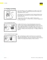
Page 20: ...d sensors 4 3 1 Testing the Sensors In order to test the sensors the actual temperature at each sensor location must be measured A good quality digital thermometer with a surface temperature probe is recommended for ease of use and accuracy Where a digital thermometer is not available a spare sensor can be strapped alongside the one to be tested and the readings compared Test the sensors according...

Page 21: ... prevents firing until the boiler pump is running If the boiler operates properly disconnect the power and remove the jumper 4 3 3 2 Boiler 4 3 4 Connecting the Control Make sure all power to the devices and terminal blocks is off and remove any remaining jumpers from the terminals Reconnect the terminal blocks to the control by carefully aligning them with their respective headers on the control ...

Page 22: ...osition the control will close the boiler contact under normal conditions Refer to section 3 8 2 Boiler Enable on page 12 for a description of the Boiler Enable DIP 4 4 3 Bloc Station The Bloc Station switch is used to select which method the system will use to adjust supply water temperature The Mixing Station Enhanced Mixing Station and Diverting Valves use the Three Position Actuator Part Numbe...

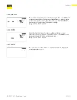
Page 23: ... is also the default display for the control Measured room air temperature as measured by the indoor sensor Only visible when Indoor Sensor is connected Current mixed supply water temperature as measured by the supply sensor Target mixed supply is the temperature the control is currently trying to maintain at the supply sensor Only visible with the Advanced Installer DIP switch set to Advanced 4 5...

Page 24: ... control operation The desired room temperature Range 35 F to 100 F The design outdoor temperature used for calculating heat loss Obtained from the Design Outdoor Temperature Chart or Viega s Radiant Wizard Range 60 F to 32 F The design supply water temperature obtained from the Supply Water Temperature BTU Output Chart or Viega s Radiant Wizard Range 70 F to 220 F The design indoor air temperatur...

Page 25: ...Set higher than MIX DSGN and account for the heat loss of distribution piping Range 80 F to 210 F or OFF Warm Weather Shut Down the design outdoor air temperature at which the control only operates in exercising mode only visible with the Advanced Installer DIP switch set to Advanced Range 35 F to 100 F or OFF The units of measure that all of the temperatures are to be displayed in the control eit...

Page 26: ... Test button until the appropriate device and segment in the display turn on 4 7 2 Testing Sensors A good quality test meter capable of measuring up to 5 000kΩ 1kΩ 1000Ω is required to measure the sensor resistance In addition to this the actual temperature must be measured with a good quality digital thermometer If a thermometer is not available a second sensor can be placed alongside the one to ...

Page 27: ...40 4 26 099 45 7 22 763 50 10 19 900 55 13 17 436 60 16 15 311 65 18 13 474 70 21 11 883 75 24 10 501 80 27 9 299 85 29 8 250 Table 1 Sensor Resistance Temperature Resistance F C Ω 90 32 7 334 95 35 6 532 100 38 5 828 105 41 5 210 110 43 4 665 115 46 4 184 120 49 3 760 125 52 3 383 130 54 3 050 135 57 2 754 140 60 2 490 145 63 2 255 150 66 2 045 155 68 1 857 160 71 1 689 165 74 1 538 170 77 1 403 ...

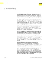
Page 28: ...through the test sequence as described in the Testing section Pause the control as necessary to ensure that the correct device is operating as it should Sketch the piping of the system This is a relatively simple step that tends to be overlooked however it can often save hours of time in troubleshooting a system Note flow directions in the system paying close attention to the location of circulato...

Page 29: ...e is too low or that the supply water high limit MIX MAX has been reached If the supply temperature is close to MIX MAX then this setting must be increased to provide more heat if possible without damaging floors Otherwise increase the MIX DSGN temperature which will increase the supply water temperature by increasing the slope of the heating curve If the building is too cool in warm weather incre...

Page 30: ...he control after the sensor has been repaired press the Item button The control is no longer able to read the Outdoor sensor due to an open circuit In this case the control assumes an outdoor temperature of 32 F 0 C and continues operation Locate the problem as described in Section 5 7 To clear the error message from the control after the sensor has been repaired press the Item button The control ...

Page 31: ...to a short circuit The control will continue to operate as if there was nothing connected to the Indoor sensor input Locate the problem as described in Section 5 7 To clear the error message from the control after the sensor has been repaired press the Item button The control is no longer able to read the Indoor sensor due to an open circuit The control will continue to operate as if there was not...

Page 32: ...trical Schematic Wiring 1 This drawing shows system wiring concept only Installer is responsible for all equipment and detailing required by local codes 2 All wiring shall be in conformance with the latest edition of the National Electrical Code 3 Maximum current rating of Basic Heating Control Relay is 10 Amps Basic Snow Melting Control Relay is 5 Amps maximum current rating of Zone Control Relay...

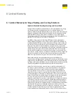
Page 33: ... 1420 g enclosure black PVC plastic Dimensions 6 5 8 H x 7 9 16 W x 2 13 16 D 170 x 193 x 72 mm Approvals CSA C US meets ICES FCC regulations for EMI RFI Ambient Conditions Indoor use only 32 to 102 F 0 to 39 C 90 RH non condensing Power Supply 120V AC 10 50 60 Hz 1300 VA Floating Output 24V AC 0 34 A 8 VA Relays 240V AC 10 A 1 3 hp pilot duty 240 VA Sensors NTC thermistor ...

Page 34: ...llation Power tools and jaws used with press fittings are warranted by the manufacturer and Viega extends no separate warranty on those tools or jaws Viega warrants that PEX press hand and pneumatic PEX hammer tools sold by Viega under normal conditions of use shall be free from failure caused by manufacturing defects for a period of two 2 years from date of sale Under this limited warranty you on...

Page 35: ... repair or replacement charges resulting from the failure or leak and additionally will reimburse damages to personal property resulting from the failure or leak After the first ten years of the time period covered by this warranty the EXCLUSIVE and ONLY remedy will be reimbursement for repair and replacement of the product covered by this warranty VIEGA SHALL NOT BE LIABLE FOR CONSEQUENTIAL ECONO...

Page 36: ... Plus and Viega Connected in quality are trademarks of Viega Holding GmbH Co KG Eco Brass is a registered trademark of Mitsubishi Shindoh Co LTD RIDGID is a registered trademark of RIDGID Inc LoopCAD is a registered trademark of Avenir Software Inc Radel R is a registered trademark of Solvay Advanced Polymers LLC LEED is a registered trademark of the U S Green Building Council Viega LLC 585 Interl...

Reviews: