5 of 13
Product
Instructions
PI-PR 566440 0114 (Programmable Heat-Cool Thermostat)
Viega LLC, 301 N. Main, 9th Floor • Wichita, KS 67202 • Ph: 800-976-9819 • Fax: 316-425-7618
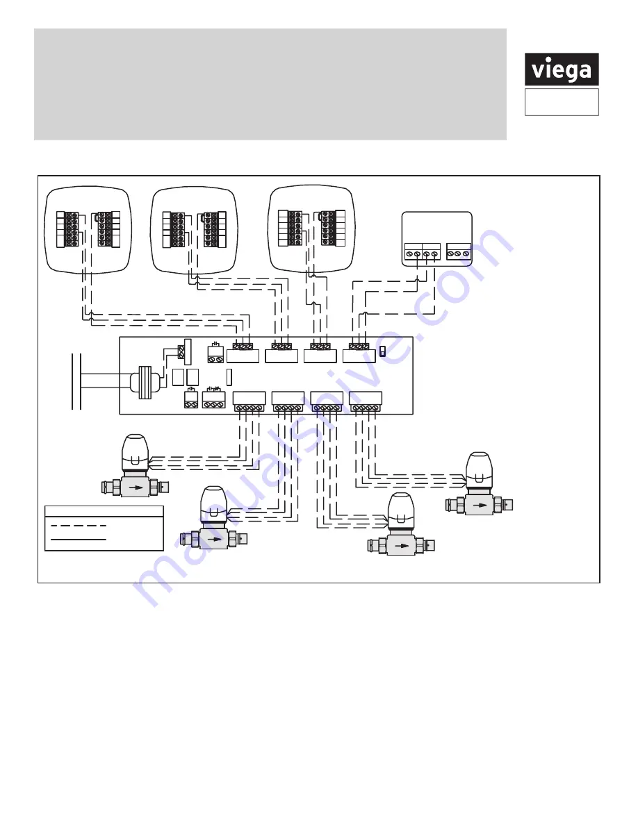
Viega wiring diagrams
ZONE CONTROL (18060, 18062)
WITH OPTIONAL PRIORITY
OFF
ON
ZONE 4 PRIORITY
ZONE 1
ZONE 2
ZONE 3
ZONE 4
ZONE 4 RELAY
N/O
N/C
COM
PUMP
END
SWITCH
ISOLATED
END
SWITCH
ZONE 1
ZONE 2
ZONE 3
ZONE 4
FUSE
(5 AMP MAX)
POWER IN
WC
R
W C
R
W C
R
WC
R
1 2 3 4
120 V AC
Power Supply
L
N
R
C
C C R W
NTC A/B
Thermostat -18050
1 2 3 4
1 2 3 4
C
O
B
W
RH
RC
G
Y
Thermostat -15116
C
O
B
W
RH
RC
G
Y
Thermostat -15117
C
O
B
W/E
RH
G
Y
Thermostat -15118
W2
Y2
RC
Viega
Yellow
Yellow
Red
Red
Viega
Yellow
Yellow
Red
Red
Viega
Yellow
Yellow
Red
Red
Viega
Yellow
Yellow
Red
Red
Line Voltage
Low Voltage
LEGEND: Zone Controls
Part Numbers:
15116, 15117 and 15118
1. Connect the "RH" terminal
from the thermostat to "R"
terminal on the zone control
2. Connect the "W" terminal
from the thermostat to "W"
terminal on the zone control,
for part number 15118
connect "W/E" terminal from
the thermostat to "W" terminal
on the zone control
3. Connect the "C" terminal from
the thermostat to the "C"
terminal on the zone control
Connecting Viega thermostats and zone valves to the Viega zone control


