background image

VIEGA • 

Viega... The global leader in plumbing and heating systems.

301 N. Main, Floor 9 • Wichita, KS 67202 • Ph: 877-Viega-NA • Fax: 800-976-9817 • E-Mail: service@viega.com • www.viega.com

Product Instructions

Basic Digital Setpoint Control II

PI-PR-17023 05/08

2 of 5

Installation

Digital Setpoint Control II 
with watertight sensor (17029)
Watertight Sensor (17031)

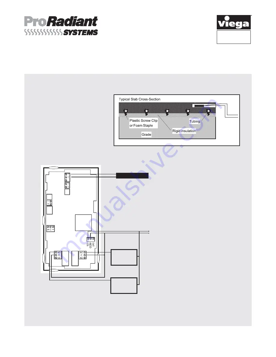
For proper control, the sensor for 
the  setpoint control must be located 
within the heating and or cooling slab.  
The  sensor  should  be  placed  midway          
between rows of tubing, and should be 
placed in conduit which is cast into the 
slab, so that replacement is possible.

SENSOR B

SENSOR A

SENSOR B

24VAC 
SUPPLY 

120V, 240V        
  SUPPLY 

RELAY 1

RELAY 2

Wiring

Digital Input

LOAD 2

LOAD 1

Sensor A is triggering the two relays, 
Relay 1 being boiler circulator pump, 
and Relay 2 being system circulator 
pump.  In heating mode, when the 
sensor detects temperature lower than 
the selected setpoint minus the selected 
differential both relays will be energized. 
When the temperature reaches the 
setpoint the relays will de-energize.

Note: 

If using 24V to power the controller, the 
24V supply must be connected to 
terminals that are , C on the 
left side of the control.

If using 120 or 240V to power the 
controller the 120 or 240V supply must 
be connect to corresponding terminals 
clearly marked on the right side of the 
control.
When connecting the sensor connect 
both red wires to one terminal and the 
white wire to the other terminal. 
Terminals for sensor marked "T".

120 V

COM

Summary of Contents for ProRadiant SYSTEMS Basic Digital Setpoint Control II

Page 1: ... basic heating and or cooling system control for commercial and residential slab application Features Setpoint Control for Heating and Cooling Simple installation and programming Large digital LCD display Reliable economical Two relay outputs with individual Setpoint capability Watertight Sensor included Specifications Digital Setpoint Control II with watertight sensor 17029 Watertight Sensor 1703...

Page 2: ... 120V 240V SUPPLY RELAY 1 RELAY 2 Wiring Digital Input LOAD 2 LOAD 1 Sensor A is triggering the two relays Relay 1 being boiler circulator pump and Relay 2 being system circulator pump In heating mode when the sensor detects temperature lower than the selected setpoint minus the selected differential both relays will be energized When the temperature reaches the setpoint the relays will de energiz...

Page 3: ...the right arrow to accept and return to Relay 1 menu 8 Select Sensor A or Sensor B for Relay 1 using the up and down arrows then press right arrow button to accept 9 Select Heat Cool option for Relay 1 then press right arrow button 10 Once you have completed all of the steps either press the HOME key or scroll down using the down arrow to EXIT and then press the right arrow button 11 Repeat all st...

Page 4: ...f the setpoint configuration is correct disconnect the sensor and check its resistance Replace the sensor if its resistance value does not match the temperature in the accompanying chart to the right Temp F Temp C Resistance Ohms 40 40 0 851 30 34 4 872 20 28 8 893 10 23 3 914 0 17 7 935 10 12 2 956 20 6 6 977 30 1 1 998 40 4 4 1019 50 10 0 1040 60 15 5 1061 70 21 1 1082 80 26 6 1103 90 32 2 1124 ...

Reviews: