46
Hardware Set-Up Procedures
IM-HC 599871 0321 RABS
4.2.1 Setting the Power Level at the Circuit Hub
The power level setting of each circuit is periodically indicated by the
color, and number of LED flashes on the circuit hub.
Power level 5 is the factory default setting.
Power level 1 = return temperature is 20 deg F less than the supply
temperature.
Power level 10 = return temperature is 2 deg F less than the supply
temperature.
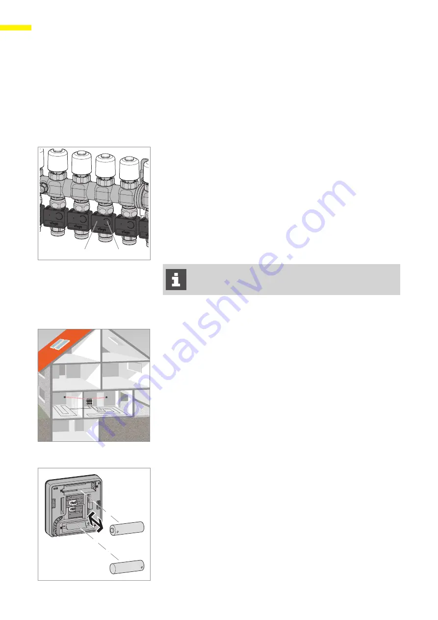
1 - Button
2 - LED
X
To check the current power level setting on a circuit, monitor
the circuit hub until it begins to flash. The power level setting
corresponds to the number of red LED flashes. When the LED
flashes green once, that means the circuit is controlled by a
thermostat.
X
To change the power level, press and hold the button on the front of
the circuit hub until the LED begins to flash.
X
Release the button when the number of flashes correlates with the
desired power level.
The power level can be changed at any time during
operation via the circuit hub or the operation software.
4.3 Method 2
–
Zone Control via Thermostat
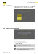
The control unit transceiver communicates with the thermostat(s) and
range extender(s) at 916 MHz. The WLAN module operates at a different
frequency, therefore these two functions are independent of each other.
It is important to check a thermostat's signal strength before selecting an
installation location for either the control unit or the thermostat. Building
materials, other electronic devices, and other radio frequencies could
influence the signal integrity. If the thermostat signal is too weak at the
desired installation location, a different location for either the control unit
or the thermostat needs to be chosen. Alternatively, a range extender can
be placed between the control unit and the thermostat.
If the range extender accessory is chosen, note the power adapter cord
length (39 inches), and use the logged in thermostat's signal strength
indicator to locate the range extender near a wall outlet.
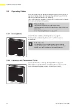
4.3.1 Inserting the Batteries — Commissioning
X
Keep the “+” and “-” buttons pressed while inserting the batteries.
Ensure that the battery orientation matches the polarity markings in
the battery compartments of the thermostat.
Z
The LEDs flash red.
1
2
EG
1.OG


