3
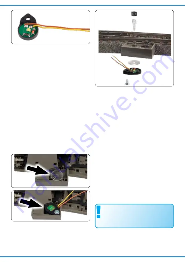
Fig. 1
Abb. 1
Fig. 2
Abb. 2
Fig. 3
Abb. 3
Fig. 4
Abb. 4
3.
Stecken Sie den passenden (kurz oder lang) La
-
ternenkörper von oben durch die dafür vorgese
-
hene Bohrung neben dem Handsteuerhebel der
Weiche. Achten Sie dabei darauf, dass der La
-
ternenkörper passend zur Weichenstellung steht:
Abzweig = Laternenkörper quer zur Fahrtrichtung
(Abbildung 2).
4.
Stecken Sie auf der Unterseite der Wei-
che die Lichtverteilerscheibe mittig auf den
quadratischen Dorn des Laternenkörpers.
Achten Sie darauf, dass der kleine schwarze He
-
bel der Weichenschaltung in das Langloch in der
Scheibe greift (Abbildung 3).
5.
Schrauben Sie nun den Montagering mit der Be-
leuchtungsplatine gemäß Abbildung 4 über die
Lichtverteilerscheibe.
6.
Stecken Sie das passende schwarze La-
ternengehäuse auf den Laternenkörper.
Achten Sie darauf, dass der Abzweigpfeil mit der
Richtung der Weiche übereinstimmt.
Achten Sie darauf, dass die Anschlusskabel der La
-
terne sich nicht in der Mechanik der Weiche verha-
ken und diese blockieren können.
Prüfen Sie, ob sich die Laterne beim Stellen der
Weiche passend zur Stellrichtung mitdreht.
2.
Place the lighting board into the mounting ring.
Observe the correct position of the yellow and
brown cables. (See figure 1)
3.
Put the lantern body from above through the re-
spective hole nearby the switching lever. Pay at
-
tention, that the lantern body has the appropriate
position to the position of the turnout: turnout =
lantern body is crosswise to the direction of trav
-
el. (see figure 2)
4.
At bottom of the turnout, put the light diffusion
disk onto the square end of the lantern body.
Pay attention that the small black lever of the
switch fits into the long hole of the disk.
5.
Screw the mounting ring with the lighting board
over the light diffusion disk onto the turnout as
shown in figure 4.
6.
Put the appropriate black lantern case onto the
transparent lantern body. Observe that the ar-
row and the direction of the turnout are similar.
Pay attention that the connection cables don’t
block the mechanics. Check if the lantern rotates
when the turnout switches.
5. Connection
The operating voltage of the switch lantern
is 14 – 16 V AC / DC.
All mounting and connection works must
only be executed after the power supply is
cut off.
Only use model railway transformers build
according to VDE / EN!
Fitting cables:
We recommend to take a flex with
a diameter of 0,14 mm² (e.g.
Viessmann
ref.-nr.
6860 – 6869 or 68603 – 68693).
5. Anschluss
Die Betriebsspannung der Weichenlaterne
beträgt 14 – 16 V = / ~.
Geeignete Kabel
: Wir empfehlen Litze mit einem
Querschnitt von 0,14 mm² (z. B.
Viessmann
Art.
Nr. 6860 – 6869 oder 68603 – 68693).


