23
DN 125
10
60
50
40
30
20
20
40
50 60
80
100
10
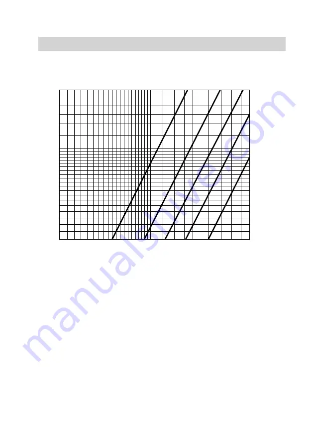
Pressure drop in Pa
Air flow rate in m³/h
0
5
-5
-10
A
10
30
70
90
A
Valve cone setting in mm
1.
Determine the required valve cone
setting from the diagram (for
DN 100 or DN 125) subject to the
intended pressure drop and air flow
rate for the section.
Example:
The design provides the following
details for the part section:
■ Extract air valve for wall and ceiling
installation: DN 100
■ Pressure drop: 20 Pa
■ Air flow rate: 35 m
3
/h
Valve cone position: 0 mm
2.
Set the determined valve cone posi-
tion
A
at the extract air valve for set-
ting into a wall or ceiling.
3.
Record the actual value in the com-
missioning report.
Commissioning, inspection, maintenance
Further details regarding the individual steps
(cont.)
5608 999 GB


