28
A B C
D
E
1.
Determine the required valve setting
from the diagram subject to the inten-
ded pressure drop and air flow rate
for the section.
Example:
The design provides the following
details for the part section:
■ Kitchen extract air valve: DN 125
■ Pressure drop: 40 Pa
■ Air flow rate: 65 m
3
/h
Valve position:
C
2.
Make the determined valve setting at
kitchen extract air valve
A
-
E
.
3.
Record the actual value in the com-
missioning report.
Duct system (flat) plastic: Pre-selecting the supply/extract air
apertures
With plastic (flat) duct systems, the flow
rate is adjusted by means of the restric-
tors at the air distribution boxes.
Installation instructions
Note
All supply air and extract air valves must
be fully opened (select max. annular
gap/valve cone setting, see pressure
drop diagrams).
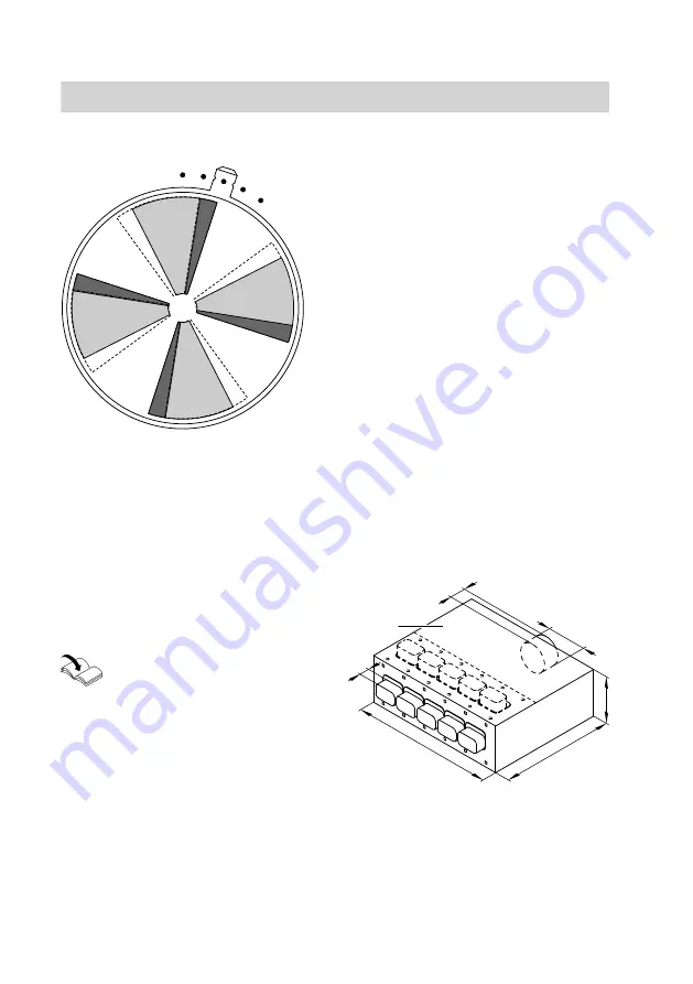
Air distribution boxes
The flat duct connectors can be fitted to
the air distribution boxes either at the
front or at an angle of 90°.
Ø125
510
210
44
70
630
A
Commissioning, inspection, maintenance
Further details regarding the individual steps
(cont.)
5608 999 GB


