50
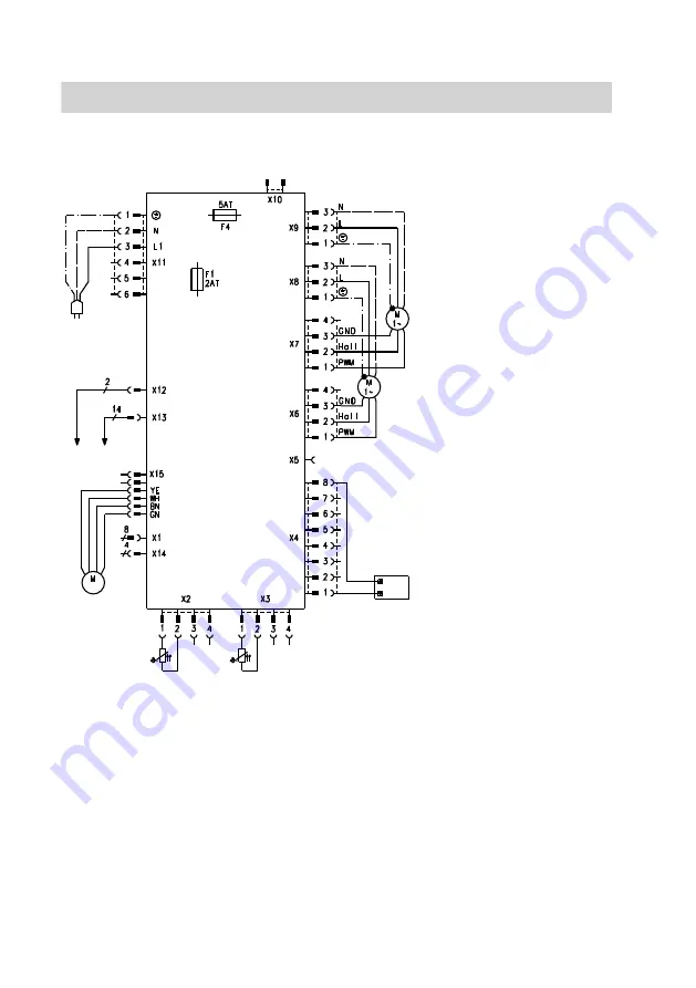
Control PCB
A
K L
H
G
F
E
D
B
C
A
Power supply 230 V/50 Hz
B
Extract air fan
C
Supply air fan
D
OpenTherm BUS connection
E
Remote control
F
Outdoor air temperature sensor
Pt 500
G
Extract air temperature sensor
Pt 500
H
Motor bypass damper
K
To the auxiliary PCB, terminal X6
L
To the auxiliary PCB, terminal X10
F1 Fuse, 2.0 A (slow), 250 V~
F4 Fuse, 5.0 A (slow), 250 V~
Connection and wiring diagram
Connection and wiring diagram
5608 999 GB


