51
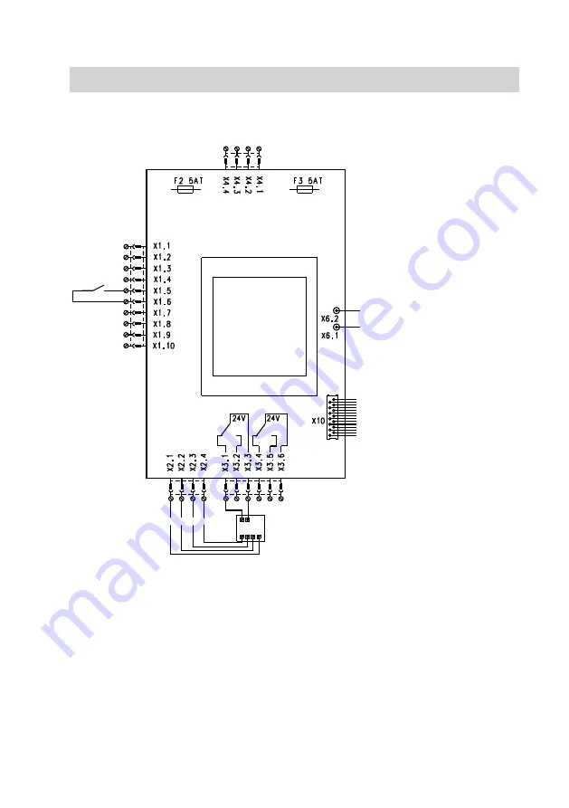
Auxiliary PCB
R
K
L
M
P N
K
To control PCB, terminal X12
L
To control PCB, terminal X13
M
CO
2
/humidity sensor, supply volt-
age 24 V~
N
Signal CO
2
capture
P
Signal humidity capture
R
Terminals X1.5/X1.6:
Connection for interlock system to
lock-out the Vitovent in the case of
negative pressure inside the room
F2 Fuse, 5.0 A (slow), 250 V~
F3 Fuse, 5.0 A (slow), 250 V~
Connection and wiring diagram
Connection and wiring diagram
(cont.)
5608 999 GB


