19
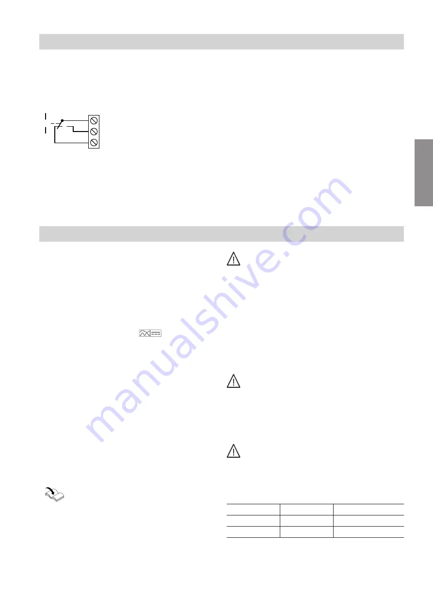
Contact humidistat signal 24 V
–
If a contact humidistat has responded, this response
can be made available as a signal via a floating
changeover contact.
X4.8
X4.9
X4.7
[YA
K
Fig.12
X4 Low voltage terminal strip on the AC-Box PCB,
contact breaking capacity 10 to 30 V, 5 A
X4.7 Contact humidistat has responded.
X4.9 Contact humidistat has not responded.
Power supply
Isolators for non-earthed conductors
■
Install an isolator in the power cable to provide
omnipolar separation from the mains for all active
conductors, corresponding to overvoltage category
III (3 mm) for full isolation. This isolator must be fitted
in the permanent electrical installation in line with
installation requirements, e.g. mains isolator or
upstream circuit breaker.
■
We additionally recommend installing an AC/DC-
sensitive RCD (RCD class B
) for DC (fault)
currents that can occur with energy efficient equip-
ment.
■
Class A RCDs must
not
be used and not installed
upstream of the class B RCD.
Connection information
■
The "Mains" power cable is connected to the AC-Box
PCB and routed to the outside of the unit at the fac-
tory.
■
We recommend connecting the power supply for the
AC-Box at the power supply of the heat pump control
unit.
Connection to the same fuse provides additional pro-
tection in the case of faults and when the power is
switched off. For this, take the power consumption of
the connected consumer into account (fuse protec-
tion, heat pump control unit, max. 16 A).
Heat pump installation and service instructions
Danger
Incorrect electrical installations can lead to seri-
ous injury from electrical current and result in
appliance damage.
Connect the power supply and implement all
safety measures (e.g. RCD circuit) in accord-
ance with the following regulations:
■
IEC 60364-4-41
■
VDE regulations
■
Technical connection requirements specified
by the local power supply utility
■
Protect the power cable with a fuse/MCB of
max. 16 A.
Danger
The absence of system component earthing can
lead to serious injury from electrical current and
component damage in the event of an electrical
fault.
The appliance and pipework must be connected
to the equipotential bonding of the building.
Danger
Incorrect core assignment can lead to serious
injury from electrical current and result in equip-
ment damage.
Never interchange cores "L" and "N".
Colour coding to IEC 60757
L
BN
Brown
N
BU
Blue
?
GNYE
Green/yellow
Installation sequence
Electrical connection
(cont.)
5675 895 GB
Installation


