106
1.
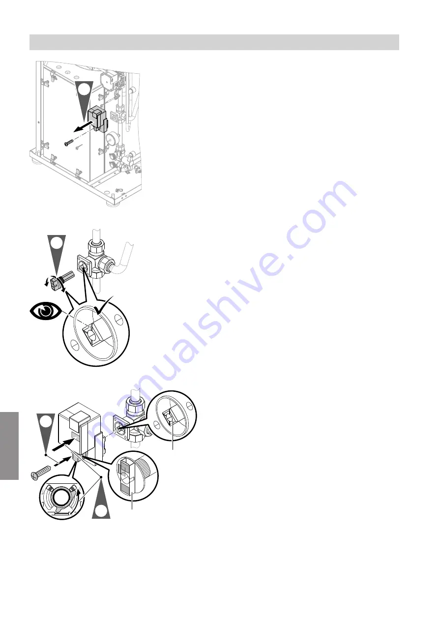
Fig. 59
1.
Undo the screw and remove the rotary selector
with drive motor.
2.
Fig. 60
2.
Pull the rotary selector off the drive motor and
insert it into the control valve. Turn the control
valve to the left as far as it will go.
A
3.
4.
B
Fig. 61
3.
Re-insert the drive motor and rotary selector, note
the position of the rotary selector when doing so.
The markings of valve shaft
A
and motor shaft
B
must be corresponding.
Note
Take care not to twist or tilt the toothed metal disc,
otherwise the thread of the screw will not grip.
4.
Re-secure the drive motor and rotary selector with
the screw.
Maintenance
Setting the control valve motor position
5678 044 GB
Maintenance
Summary of Contents for D2RA
Page 113: ...113 Maintenance Checking the Vitotronic 200 H accessories cont 5678 044 GB Maintenance ...
Page 133: ...133 Parts lists Sorption module hydraulics cont 5678 044 GB Components ...
Page 136: ...136 0001 0002 0003 0004 0005 Fig 83 Parts lists Miscellaneous 5678 044 GB Components ...
Page 163: ...163 5678 044 GB ...


