12
50
600
43
50
K
85
462
L
220
330
216
596
D
E
B
A
C
H
735
40
F
1422
1477
1588
1698
1753
316
398
410
A
B
D
C
E
E
D
C
B
A
110
225
38
F
1159
290
55
1941
1875
1976
G
H
G
727
819
177
55
K
L
2038
152
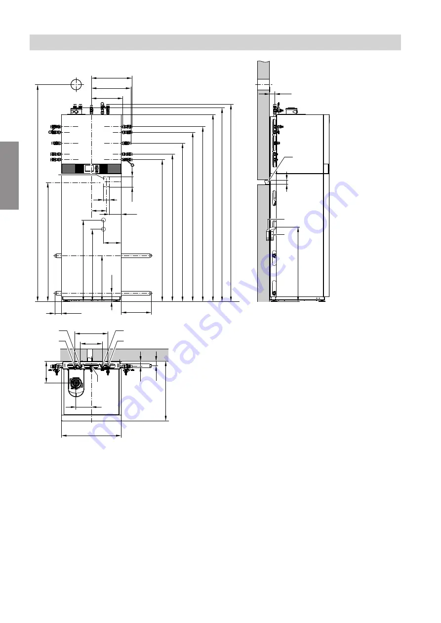
Fig. 2
A
Heating flow R
¾
B
DHW cylinder flow R
¾
C
Gas connection R
½
D
DHW cylinder return R
¾
E
Heating return R
¾
F
Wiring area
G
Condensate hose to the rear and into the wall, to
the left or to the right
H
Safety valve discharge pipe to the rear and into the
wall, to the left or to the right
K
Primary circuit flow (natural heat source inlet) G
¾
L
Primary circuit return (natural heat source outlet)
G
¾
Note
All height dimensions have a tolerance of +30 mm due
to the adjustable feet.
Preparing for installation
Installation preparations
(cont.)
5678 044 GB
Installation
Summary of Contents for D2RA
Page 113: ...113 Maintenance Checking the Vitotronic 200 H accessories cont 5678 044 GB Maintenance ...
Page 133: ...133 Parts lists Sorption module hydraulics cont 5678 044 GB Components ...
Page 136: ...136 0001 0002 0003 0004 0005 Fig 83 Parts lists Miscellaneous 5678 044 GB Components ...
Page 163: ...163 5678 044 GB ...


