21
AB
C D
D
C
B
A
A
B
C
D
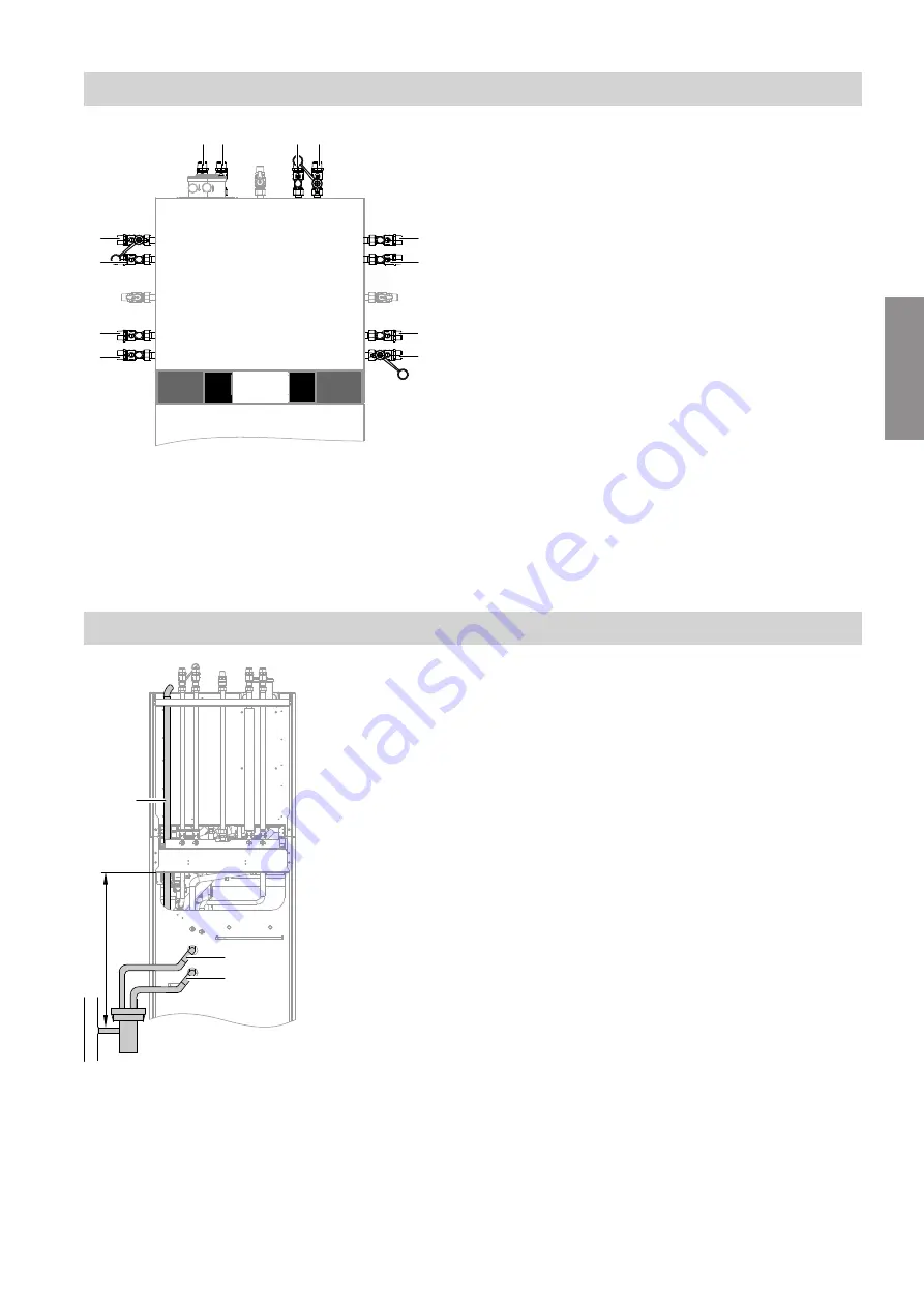
Fig. 9
A
Heating flow R
¾
B
DHW cylinder flow R
¾
C
DHW cylinder return R
¾
D
Heating return R
¾
Condensate connection
B
A
> 200
C
Fig. 10
1.
Route vent hose
A
upwards. Secure vent hose to
the bracket with a cable tie.
2.
Route condensate hose
B
and safety valve dis-
charge pipe
C
to the rear to the wall, or to the left
or right to the side aperture.
Note
Pull condensate hose and safety valve discharge
pipe far enough out of the appliance to prevent
unnecessary bends inside the appliance.
3.
Connect condensate hose and safety valve dis-
charge pipe to drain outlet set with integral siphon
(accessories).
Or
Connect condensate hose and safety valve dis-
charge pipe to an on-site siphon. Ensure that the
siphon is connected securely.
Note
Connect the condensate pipe with a constant fall to
the public sewage system with an additional pipe
vent, or to a neutralising system.
Installation sequence
Connections on the secondary side
(cont.)
5678 044 GB
Installation
Summary of Contents for D2RA
Page 113: ...113 Maintenance Checking the Vitotronic 200 H accessories cont 5678 044 GB Maintenance ...
Page 133: ...133 Parts lists Sorption module hydraulics cont 5678 044 GB Components ...
Page 136: ...136 0001 0002 0003 0004 0005 Fig 83 Parts lists Miscellaneous 5678 044 GB Components ...
Page 163: ...163 5678 044 GB ...


