110
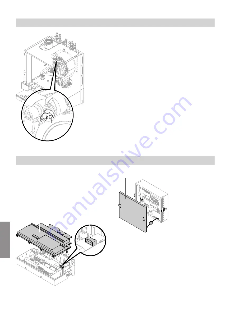
A
Fig. 67
1.
Let the appliance cool down until the temperature
falls below the switching point (95 °C).
2.
Press pin
A
on the high limit safety cut-out to
reset it.
3.
Press reset button
R
on the Vitotronic control unit.
If the fault recurs:
1.
Pull the leads from the high limit safety cut-out.
2.
Check the continuity of the high limit safety cut-out
with a multimeter.
3.
Remove the faulty high limit safety cut-out.
4.
Apply heat conducting paste to the replacement
high limit safety cut-out and install it.
5.
After commissioning, press reset button
R
on the
Vitotronic control unit.
Checking the fuses
A fuse F1 is located in the Vitotronic control unit and in
the process control unit:
■
Vitotronic control unit:
6.3 A (slow), 250 V~
Max. power loss
≤
2.5 W
■
Process control unit:
3.15 A (slow), 250 V~
Max. power loss
≤
1.4 W
Vitotronic control unit
F1
A
Fig. 68
Process control unit
F1
A
Fig. 69
1.
Switch off the power supply.
2.
Release the side closures and pivot the Vitotronic
control unit down.
3.
Remove cover
A
from the Vitotronic control unit or
process control unit.
4.
Check fuse F1.
Maintenance
Checking the high limit safety cut-out
5678 044 GB
Maintenance
Summary of Contents for D2RA
Page 113: ...113 Maintenance Checking the Vitotronic 200 H accessories cont 5678 044 GB Maintenance ...
Page 133: ...133 Parts lists Sorption module hydraulics cont 5678 044 GB Components ...
Page 136: ...136 0001 0002 0003 0004 0005 Fig 83 Parts lists Miscellaneous 5678 044 GB Components ...
Page 163: ...163 5678 044 GB ...


