background image

39

5443 109  v1.9

Pyrot Technical Data

Electrical

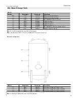
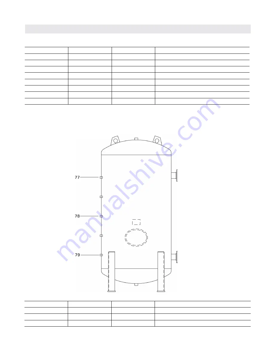
 Hot Water Storage Tank

Hot water storage tank

Number 

Designation

Device tag

Description

77

B28.1

-22B28.1

Hot water storage tank sensor (top)

78

B28.2

-22B28.2

Hot water storage tank sensor (middle)

79

B28.3

-22B28.3

Hot water storage tank sensor (bottom)

Note:

 For details on designation, see field wiring diagram.

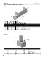
Silo Lid

Number 

Designation

Device tag

Description

69

Y6.3

-22Y6.3

Solenoid valve silo lid open

70

Y6.4

-22Y6.4

Solenoid valve silo lid close

71

S6.1

-22S6.1

Key operated switch for silo lid

72

M901

-24M901

Vibration motor 1

73

M902

-24M902

Vibration motor 2

74

M903

-24M903

Vibration motor 3

75

S901

-24S901

Key operated switch for vibration motor

76

S5.1

-68S5.1

Safety switch for silo lid

Note:

 For details on designation see field wiring diagram

Note:

 The quantity of items 79 to 81 will depend on the size of the silo lid.

Summary of Contents for KOB PYROT KRT SERIES

Page 1: ...chnology A feed auger continuously moves the wood fuel onto a moving grate where gasification takes place The combustible gases blend with precisely controlled secondary air resulting in a complete combustion with ultra low emissions Max output 150 to 540 kW 512 to 1843 MBH Min output 45 to 140 kW 154 to 478 MBH Pyrotr Product may not be exactly as shown Wood fired Boiler KRT 150 to KRT 540 Series...

Page 2: ...ratures in closed loop forced circulation hot water heating systems Under certain conditions open loop systems may also be considered Contact Viessmann for details Specifications Fully automatic rotating combustion wood fired boiler 5 models from 512 to 1843 MBH For dry wood fuels with max water content of 35 Efficiency 85 Available for 30 or 60 psi max operating pressure Benefits at a glance High...

Page 3: ...hat is burned A mechanical adjustable damper provides a constant ratio of the quantity of re circulated gas to fresh air over the entire output range The flue gas blower is specially designed for wood heating operation and is very quiet The motor has a solid heat resistant design with a heat dissipation hub and is spring supported The blower casing has a round intake port and a round blowout nozzl...

Page 4: ...ges Minimum clearances to walls for installation and maintenance work must be observed Anti vibration boiler supports may be used if anti vibration measures are required Pyrot 150 300 Hoist by the lifting lug Pyrot 400 540 Hoist by boiler supply and boiler return flanges using a lifting lug IMPORTANT WARNING Follow instructions for proper installation For wood fired installations This wood fired b...

Page 5: ...ng opening including pneumatic cleaning system 47a in x 128 in 1200 mm x 3250 mm 59 in x 128 in 1500 mm x 3250 mm 59 in x 141c in 1500 mm x 3600 mm 70c in x 145c in 1800 mm x 3700 mm 70c in x 153b in 1800 mm x 3900 mm Delivery Condition General Information Components that are not attached or installed to the boiler at time of delivery scope of the contractor Electrical components which include tem...

Page 6: ...ed by detaching additional components to the ones as described in section Standard delivery condition and Special delivery condition partially disbanded The assembly of these components require welding and additional assembly time of approximately 20 hours Measurements of the largest part for reduced boiler size Boiler model KRT150 KRT220 KRT300 KRT400 KRT540 Minimum size door 35b in x 49a in 900 ...

Page 7: ...used Viessmann will not assume any liability for the functioning or service life of the boiler plant Refer to the Warranty section in the General Terms and Conditions of Delivery Burn wood only Do not use chemicals or fluids to start fire Do not burn garbage gasoline naphtha engine oil or other inappropriate materials IMPORTANT General Information The PYROT is only suitable for burning fuels liste...

Page 8: ...on a S130 8 1 W10 to W20 C1 Sawdust untreated planing shop b1 S200 12 5 W20 to W35 C1 Sawdust untreated sawmill c2 S250 15 6 W35 to W50 C1 Sawdust untreated sawmill Wood chips Fuel code Bulk Density kg m lb ft Water content Fuel Size Description b2 S200 12 5 W20 C7 Forest wood chips soft untreated c1 S250 15 6 W20 to W35 C7 Forest wood chips soft untreated d1 S300 18 7 W20 to W35 C7 Forest wood ch...

Page 9: ...or plastics The following limits per lb kg of dry fuel of contained non combustible substances apply ash analyzed at a temperature of 1500 F 815 C Substance Limit Comparative value untreated forest wood Chlorine Cl max 300 ppm 300 mg kg 10 ppm 10 mg kg Sulphur S max 1000 ppm 1000 mg kg 120 ppm 120 mg kg Total Cl S max 1000 ppm 1000 mg kg 130 ppm 130 mg kg Ash content total max 0 25 oz lb 15 0 g kg...

Page 10: ... failure the boiler will be reliably cooled by the thermal run off safety valve Power Failure Provision Safety Venting Requirements For installations in Canada The boiler venting system must be tested and listed by a Nationally Recognized Testing Lab such as ULC CSA for solid fuel burning appliances The PYROT rotating combustion system is output controlled within a range from 30 100 of the rated b...

Page 11: ... filling with water and fuel The load bearing capacity of the floor in the area of the boiler bearing surface must be 512 lb ft 2500 kg m IMPORTANT Always follow the most up to date local municipal and building regulations and codes x Fuel feed to the boiler y Heat resistant floor Surface medium grey Boiler supporting surface Ensure the mechanical room complies with the requirements in these instr...

Page 12: ...pplicable local codes In the absence of local codes use CSA B365 01 Installation Code for Solid Fuel Burning Appliances and Equipment Always use latest edition codes Confined spaces When a furnace or boiler is enclosed in a space that has a volume less than 20 of that to be heated by the appliance the space shall a have a permanent opening or openings for natural air circulation with a minimum net...

Page 13: ... F C 13 38 114 430 116 3 10 8 99 374 8 32 30 76 209 790 172 3 16 0 197 744 12 45 16 42 238 900 222 9 20 7 233 883 15 55 11 29 350 1330 310 1 28 8 354 1340 20 75 22 56 399 1510 424 1 39 4 426 1613 24 91 24 90 60 or 90 4 or 6 30 or 60 2 or 4 250 120 149 65 Weight Weight of fire box Weight of pressure vessel 30 psi 6 Weight of pressure vessel 60 psi 6 Weight of displacement rods Weight of flue gas bl...

Page 14: ...5 5 DN 125 h in mm 12213 16 3120 13413 16 3424 14813 16 3780 157f 4004 1665 8 4232 k in mm 149 16 370 149 16 370 175 16 440 175 16 440 249 16 548 l in mm 34a 870 45a 1150 45a 1150 54c 1390 54c 1390 m in mm 69b 1765 7911 16 2024 7911 16 2024 891 16 2262 9113 16 2332 n in mm 717 8 1825 821 16 2084 821 16 2084 95e 2422 1 98d 2492 1 o in mm 279 16 700 279 16 700 279 16 700 279 16 700 293 16 742 p in m...

Page 15: ...Mechanical Dimensions Boiler Model KRT 150 220 300 400 540 a in mm 119b 3035 120b 3059 1347 16 3415 136d 3457 1451 16 3685 b in mm 889 16 2250 89b 2274 1039 16 2630 10215 16 2614 1117 16 2842 Legend A Boiler Return B Boiler Supply C Automatic de ashing system optional ...

Page 16: ...ht barrier for in feed auger K Limit switch for maintenance cover L Temperature sensor for in feed auger M Light barrier for ember monitoring 2 locations N Light barrier for automatic de ashing system Legend A Pneumatic cleaning system optional B Cleaning cover flue gas collector alternate port for the flue gas blower C Cover with sight glass D Recirculation gas line line routing variable E Automa...

Page 17: ...3 16 249 1213 16 319 1213 16 319 117 8 301 117 8 301 x in mm 40 1023 40 1023 47 1193 501 8 1273 557 16 1408 Connection station with moveable ash bin mountable at 90 and thus making it possible to select the direction in which it moves out Standard variations and A D are also possible in mirror inverted fashion Extension of ascending conveyor auger per meter Extension of de ashing auger per meter A...

Page 18: ...d out is conveyed into the container With the large base container maximum maintenance free intervals are achieved Supplied with Boiler ash chamber with ash level control system and de ashing auger made of high temperature steel powered by a worm drive motor Base container with maximum volume and two maintenance doors for removing ash by vacuum or rake Control of the de ashing by light barrier Boi...

Page 19: ...2 3300 1189 4500 A customer supplied air compressor has to deliver at least the quantity and quality of air specified and have an adjustable pressure controller as well as a safeguard against hose rupture e g operating time limiter Function of the control system The number of cleaning cycles within one time unit e g per hour is adapted to the load of the boiler One individual complete cleaning cyc...

Page 20: ...8 175 It is recommended to install a draft damper in the chimney 1 The draft damper is field supplied Optional the Viessmann supplied draft damper can be installed in the flue gas pipe of the biomass boiler 2 The draft damper should be installed in the flue gas pipe not included as close as possible to the chimney not closer than 39e In 1000 mm to the outlet of the flue gas blower The final positi...

Page 21: ...ther top or side Unused connection as cleaning cover clean gas space alternate mounting of flue gas blower shown in dark grey B Cleaning cover crude gas chamber C De duster axial cyclone D Ash bin support frame 24 USG 90 L E Recirculation gas to boiler F Flue gas to chimney Ash bin support frame positioning is possible in 4 x 90 extraction ash bin The flue gas de duster minimizes dust emissions an...

Page 22: ...d against corrosion In the case of boiler demand the filter cartridges are preheated If the set filter temperature is reached boiler start up operation is enabled If the temperature falls below the filter temperature set point the filter heating system starts in heating mode The filters are cleaned automatically in the counter current This means that the dust layer on the mesh is regularly discard...

Page 23: ...n mm 357 16 900 357 16 900 357 16 900 q in mm 4615 16 1192 4615 16 1192 47 1040 r in mm 4215 16 1069 4215 16 1069 4215 16 1069 s in mm 31b 800 31b 800 31b 800 t in mm 86f 2200 86f 2200 86f 2200 Weight Transport weight lb kg 1036 1036 470 470 1081 1081 490 490 1081 1081 470 470 Total weight lb kg 2073 940 2117 960 2161 980 Metal Mesh Filter continued Legend A Clean gas collector B Crude gas distrib...

Page 24: ... J Nipple K Pressure relief valve 30 psi or 60 psi L Safety heat exchanger connections NPTM b in 1 M Sensor well Safety Temperature Limiter STB N 3 in or 4 in Boiler supply flange 2 O Supply sensor well sensor supplied P Return sensor well sensor supplied Q 3 in or 4 in Boiler return flange 2 R Sensor well for thermal safety flush valve Rb in sensor supplied B C D F G H J K L M N O P E I A R L Q T...

Page 25: ...on port System fill System fill Piping and Installation of Safety Devices 1 2 and 3 indicates system connections Legend A Additional heat source B Storage tank as low loss header option A 3 sensors optionally 5 sensors C Distributor heat consumer D Storage tank 1 E Storage tank 2 F Two storage tanks as low loss header option B 3 sensors optionally 5 sensors G Additional heat source controlled with...

Page 26: ... the scope of supply provided by Viessmann M 20 Boiler pump Y 20 Boiler mixing valve PRV Pressure relief valve pressure set to 30 or 60 psi TS2430 Thermal run off safety valve R in approved component special purpose designed for opening at a temperature of 122 248 F 50 120 C safety heat exchanger loop built into the boiler The Pyrot 150 to Pyrot 300 have one safety heat exchanger loop and require ...

Page 27: ...speed into the fire box Back flash safeguard The PYROT Rotating Combustion System is operated with continuous negative pressure and is equipped with a backflash prevention device This device prevents backflashes caused by flying embers or combustible gases that may ignite the fuel system Automatic In feed auger extinguishing system The supplied fire extinguishing system is necessary on the in feed...

Page 28: ...able safeguard against back burn Max overpressure allowed in fuel storage unit 500 Pa 2 00 wc Max negative pressure allowed in fuel storage unit 0 Pa 0 wc Fire Protection continued IMPORTANT IMPORTANT IMPORTANT Double rotary valve with pressure compensation system If due to special circumstances any mechanically produced negative pressures or extraordinarily high overpressures are expected in the ...

Page 29: ...position 3 equals approximately 176 F 80 C The lines must be executed as hard piping in metal b in It must not be possible to shut off the cold water inlet without the aid of tools Be especially sure to comply with the instruction in the Fire Protection section The lines must be executed as hard piping in metal b in It must not be possible to shut off the cold water inlet without the aid of tools ...

Page 30: ...d air supply through motor operated air vents for the best possible combustion using a lambda sensor Upholding the return temperature with the boiler mixing value provides for a long service life of the boiler Safety functions for Excess temperature burn back opening of a lid in the loading system and forced heat dissipation Floating output malfunction combustion system Operation Operation is carr...

Page 31: ...integrated in control cabinet Parameter assignment for the drive function Input in the control cabinet for safety end switch on the maintenance cover Output in the control cabinet for external conveyor drive Infrared light barrier level monitoring system for fuel Customer supplied Delivery and or installation of safety end switch for the external conveyor drive Note Only for PYROT Starttec is buil...

Page 32: ...SCII data record via serial interface to higher level control equipment of the customer s All the adjustable parameters can be changed via the higher level control equipment as long as the control equipment provides for this Supplied with Interface on the control panel Software component MOD BUS protocol baud rate 9600 Visualization by web server Function A complete package for transmitting all da...

Page 33: ...6 Solenoid valve 6 Temperature sensors 19 B1 22B1 Flue gas temperature sensor 20 B20 22B20 Boiler supply temperature sensor 21 B20 1 22B20 1 Boiler return temperature sensor 22 B02 22B02 Infeed auger temperature sensor Light barriers 23 B1 1 16B1 1 Light barrier embers 1 Transmitter 24 B1 2 16B1 2 Light barrier embers 1 Receiver 25 B2 1 17B2 1 Light barrier embers 2 Transmitter 26 B2 2 1782 2 Ligh...

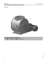
Page 34: ...34 5443 109 v1 9 Pyrot Technical Data Electrical Number Designation Device tag Description A M9 9 M9 Motor for rotary valve Rotary Valve Fuel Transport and Extraction Systems ...

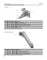
Page 35: ...arrier metering container Receiver 38 M30 1 23M30 1 Slide valve T30 39 M30 2 23M30 2 Slide valve T30 Pipe trough conveyor auger Number Designation Device tag Description 40 M32 12M32 Motor for pipe trough conveyor auger 41 S32 1 12S32 1 Limit switch for maintenance lid 42 B32 1 12B32 1 Light barrier conveyor auger Transmitter 43 B32 2 12B32 2 Light barrier conveyor auger Receiver Note For details ...

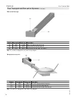
Page 36: ...switch for maintenance lid 46 S32 2 12S32 2 Limit switch for silo door not shown Note For details on designation see field wiring diagram Number Designation Device tag Description 47 M32 12M32 Motor for spring extraction system 48 S32 1 12S32 1 Limit switch for maintenance lid 49 S32 2 12S32 2 Limit switch for silo door not shown Note For details on designation see field wiring diagram Spring extr...

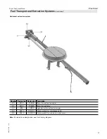
Page 37: ...m Number Device tag Device tag Description 50 M32 12M32 Motor for extraction auger 51 M33 12M33 Motor for agitator 52 B32 12B32 Light barrier for extraction auger 53 S32 1 12S32 1 Safety switch for maintenance lid 54 S32 2 12S32 2 Safety switch for silo door not shown Note For details on designation see field wiring diagram ...

Page 38: ... for walking floor auger 56 S3 68S3 Safety switch for maintenance lid 57 S3 1 68S3 1 Safety switch for auger cover 58 B3 1 61B3 1 Light barrier walking floor auger Transmitter 59 B3 2 61B3 2 Light barrier walking floor auger Receiver 60 B6 1 1 61B6 1 1 Light barrier silo distribution top Transmitter 61 B6 1 2 61B6 1 2 Light barrier silo distribution top Receiver 62 B6 2 1 61B6 2 1 Light barrier si...

Page 39: ...eld wiring diagram Silo Lid Number Designation Device tag Description 69 Y6 3 22Y6 3 Solenoid valve silo lid open 70 Y6 4 22Y6 4 Solenoid valve silo lid close 71 S6 1 22S6 1 Key operated switch for silo lid 72 M901 24M901 Vibration motor 1 73 M902 24M902 Vibration motor 2 74 M903 24M903 Vibration motor 3 75 S901 24S901 Key operated switch for vibration motor 76 S5 1 68S5 1 Safety switch for silo l...

Page 40: ...initial operation the material to be burned for the initial operation has to be at least air dry For the first three hours the heating up process should be carried out at low output To ensure that the silo extraction system is functioning properly only place a minimal amount of fuel in the silo in case there is a problem This enables the extraction system to be cleaned out quickly and the problem ...

Reviews: