47
A
Air pressure switch.............................21
Applicability........................................48
B
Burner
■ Cleaning.........................................18
■ Fitting..............................................18
Burner control unit
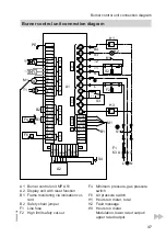
■ Connection diagram.......................37
■ DIP switch setting or parameter set24
■ Display and programming unit........22
■ Fault code.......................................29
■ Fault display...................................26
■ Fault memory..................................27
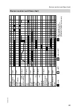
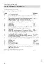
■ Flow chart.......................................35
■ Operating display............................22
■ Service display...............................24
C
Checking the burner gauze assembly16
Checking the CO2 content.................12
Checking the gas type.........................7
Checking the ignition and ionisation
electrodes..........................................17
Checking the ionisation current..........14
Checking the ionisation electrode......17
Checking the nozzle pressure............10
Checking tightness
■ Connections on the gas side..........19
■ Gas train valves..............................19
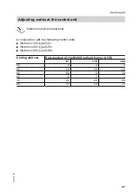
Codes at the control unit....................41
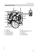
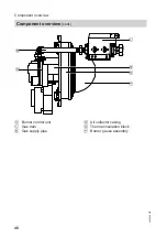
Component overview.........................39
Connection diagram...........................37
Conversion to natural gas LL...............7
D
Diagnostic table.................................29
DIP switch setting..............................24
DIP switch setting or parameter set...24
F
Fault code..........................................29
Fault display.......................................26
Fault memory.....................................27
Faults
■ With fault indication........................29
■ Without fault display.......................33
Final testing........................................20
Flow chart..........................................35
Flow pressure......................................9
I
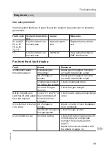
Internal system fault...........................33
M
P
Parameter set
■ Acknowledging...............................25
■ Setting............................................24
■ Settings display..............................26
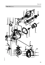
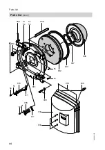
Parts list.............................................42
R
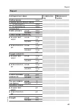
Report................................................45
Restrictor
■ Natural gas E..................................46
■ Natural gas LL................................46
S
Setting reduced output.......................24
Static pressure.....................................8
Supply pressure...................................9
System
■ Commissioning.................................6
■ Shutting down.................................15
Keyword index
Keyword index
5692 488 GB

