14
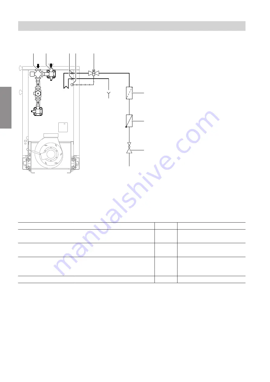
Boiler connections
A
B
C D
E
F
G
H
K
Fig. 4
A
Boiler return
B
Boiler flow
C
Thermally activated safety valve, safety heat
exchanger installed in the boiler
D
Sensor, thermally activated safety valve
E
Thermally activated safety valve
F
Particle filter
G
Check valve
H
Pressure reducer
K
Cold water connection
Connections
Output
kW
40 - 75
85 - 170
Flow
DN
32
40
R
1
¼"
1
½"
Return
DN
32
40
R
1
¼"
1
½"
Cold water supply
On site, in fixed metal pipe
2.5 to 3.5 bar (0.25 to 0.35 MPa)
DN
15
15
R
½"
½"
Cold water outlet
On site
R
¾"
¾"
Installation sequence
Hydraulic connections
5684984
Installation


