61
150
X1
151
57
41
197
198
2
17
1
15
169
9
145
X15
146
100A
203
204
D
B
A
C
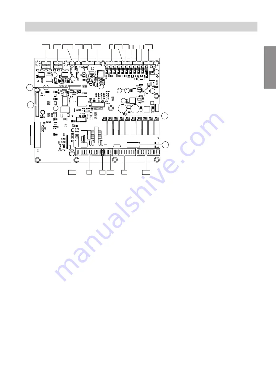
Fig. 38
A
Connection, programming unit
B
Battery
C
LED
D
MCB/fuse
s¢F
Secondary air dampers
s¢D
Primary air dampers
a¢Ö
A
Hall sensor
aVH
N/A
X15
CAN BUS
aVG
KM BUS
)
Buffer cylinder sensor
!
,
aG
and
aNL
Weather, flue gas temperature sen-
sors
?
and
aJ
FL and RT sensors
a:K
Lambda probe
a:J
N/A
fA
Flue gas fan
gJ
N/A
aBA
Fault message
X1
Buffer cylinder control valve, power
cable, boiler circuit pump, boiler valve
aBÖ
High limit safety cut-out
Connection and wiring diagram
PCB KSK 2.01b
5684984
Appendix

