10
M
Type T0S-ze only:
■
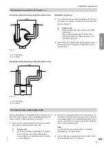
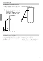
Temperature sensor, external heat generator
or
■
High limit safety cut-out for stopping the solar cir-
cuit pump
N
DHW circulation R ¾
O
DHW R ¾
P
Condensate
7
20 mm
Q
Sensor well for draw-off profile recognition
R
Power cable (3 m long)
Transport and siting
!
Please note
Impacts, compression and tensile loads can
cause damage to the outside panels of the
appliance.
Never
put weight on the top or front of the appli-
ance or cylinder jacket.
The DHW heat pump can be transported vertically or
horizontally.
Note for horizontal transport
Position the DHW heat pump. Allow the DHW heat
pump to stand for at least 24 hours before commis-
sioning.
Lifting straps (accessories) are available to facilitate
transport.
Installation room requirements
■
The installation room must be dry and free from the
risk of frost.
■
The intake air must be kept free from dust, grease
and contamination through halogenated hydrocar-
bons (e.g. as contained in sprays, paints, solvents
and cleaning agents).
■
To prevent the transmission of structure-borne noise,
never site the appliance above ceilings with wooden
joists (e.g. in the attic).
■
A separately fused standard power socket must be
available.
■
A condensate drain pipe must be available.
■
Always maintain the minimum clearances for service
and maintenance work.
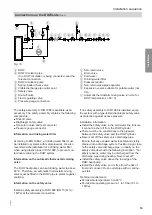
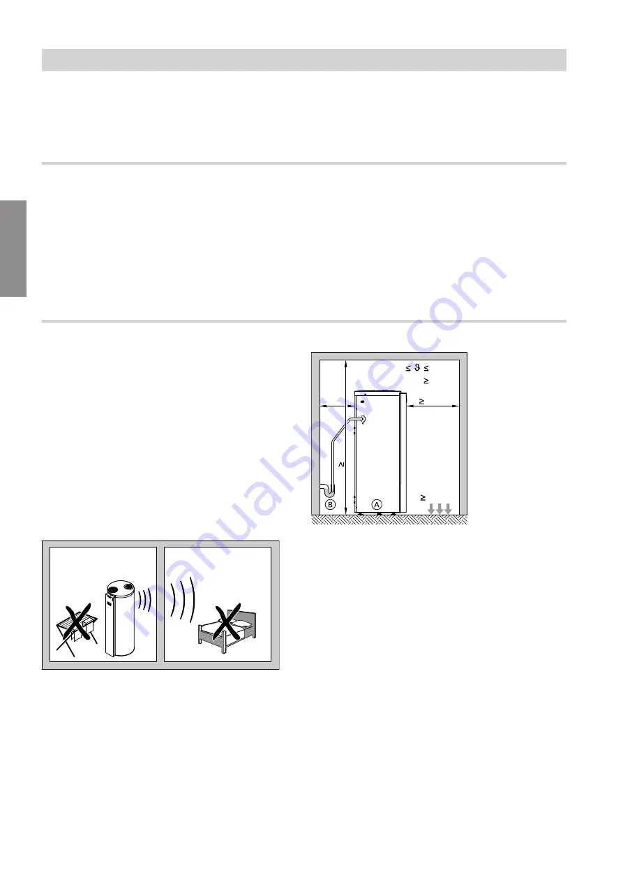
Fig. 3
Minimum clearances
Recirculation air mode
Note
The specified appliance output cannot be guaranteed if
the room volume is < 20 m
3
.
V 20 m³
2 °C
40 °C
500 kg
2000
650
100
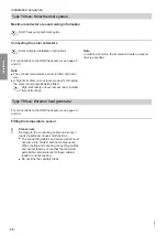
Fig. 4
A
DHW heat pump
B
Condensate drain pipe
Recirculation air mode with air discharge to the
outside
Note
■
The specified appliance output cannot be guaran-
teed if the room volume is < 20 m
3
.
■
This operating mode is only permissible in unheated
rooms.
Preparing for installation
Preparing for installation
(cont.)
6136003
Installation


