16
Information on ductwork
!
Please note
The simultaneous operation of open flue com-
bustion equipment (e.g. an open fireplace) and
the DHW heat pump in a space with combustion
air interconnection results in dangerous negative
pressure inside the room. Negative pressure
can result in flue gases re-entering the room.
■
Never
operate the DHW heat pump simultane-
ously with
open
flue combustion equipment
(e.g. an open fireplace).
■
Operate combustion equipment exclusively in
room sealed
mode with a separate supply of
combustion air. We recommend combustion
equipment with general building regulations
approval as
room sealed
combustion equip-
ment, issued by the Deutsches Institut für
Bautechnik DIBt [or local equivalent].
■
Doors to boiler rooms where the combustion
air supply is not interconnected with the living
space must be airtight and must be kept shut.
Note
In recirculation air mode with air discharge to the out-
side, ensure an adequate supply of fresh air to the
installation room (on site), e.g. via separate vents (min.
DN 160).
■
Thermally insulate the ductwork with vapour diffu-
sion-proof material.
■
Always route the ducts for air intake and air dis-
charge with a 2 to 3° fall, so that rain and conden-
sate can drain away to the outdoors.
■
Ensure air intake temperatures from -5 to 35 °C.
■
Maximum permissible total pressure drop
Δ
p
total
(ductwork and appliance): 100 Pa
■
Fit silencers to prevent flow noise.
■
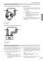
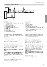
Ducts, wall outlets and connections to the DHW heat
pump can be installed using anti-vibration insulation
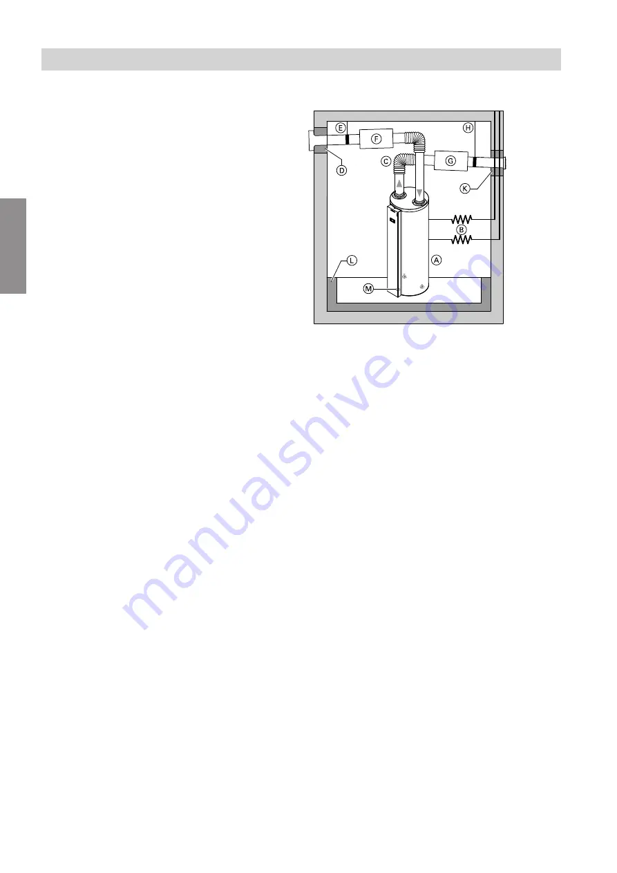
to reduce noise (see diagram).
Connections and installation options which are not per-
missible:
■
Connection of kitchen extractor hoods to the duct-
work
■
Installation of a DHW heat pump with recirculation air
mode in a heated room
■
Connection of the air intake duct to a mechanical
ventilation system
■
Connection of the air intake duct to an air/geothermal
heat exchanger
■
Connection of the air intake duct to a tumble dryer
■
Reversed connections (air intake to the outside and
air discharge to the inside)
■
Installation of the DHW heat pump in an attic
■
Installation of the DHW heat pump in dusty rooms
■
Operation of the DHW heat pump in conjunction with
an open flue boiler
Anti-vibration insulation
Fig. 11
A
DHW heat pump
B
Flexible hydraulic connections
C
EPP insulated plastic pipes or insulated flexible
pipes (min. DN 160) for air intake/air discharge
ductwork
D
Anti-vibration insulation for air intake wall duct
E
Anti-vibration bracket for air intake duct
F
Air intake silencer
G
Air discharge silencer
H
Anti-vibration bracket for air discharge duct
K
Anti-vibration insulation for air discharge wall duct
L
Anti-vibration insulation for floor
M
Adjustable feet
Measures for minimising the pressure drop
■
Use as few bends as possible.
■
As far as possible, avoid elements that increase the
pressure drop.
■
Route the air intake duct above the air discharge
duct if possible.
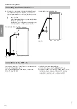
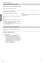
Positioning of air intake and air discharge aper-
tures
!
Please note
An "air short circuit" will result in the cooled dis-
charged air being drawn back in to the unit. This
can result in reduced heat pump efficiency and
defrosting problems.
Position the air intake and air discharge aper-
tures so that any "air short circuit" is prevented.
Installation sequence
Conversion to outdoor air mode
(cont.)
6136003
Installation


