17
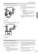
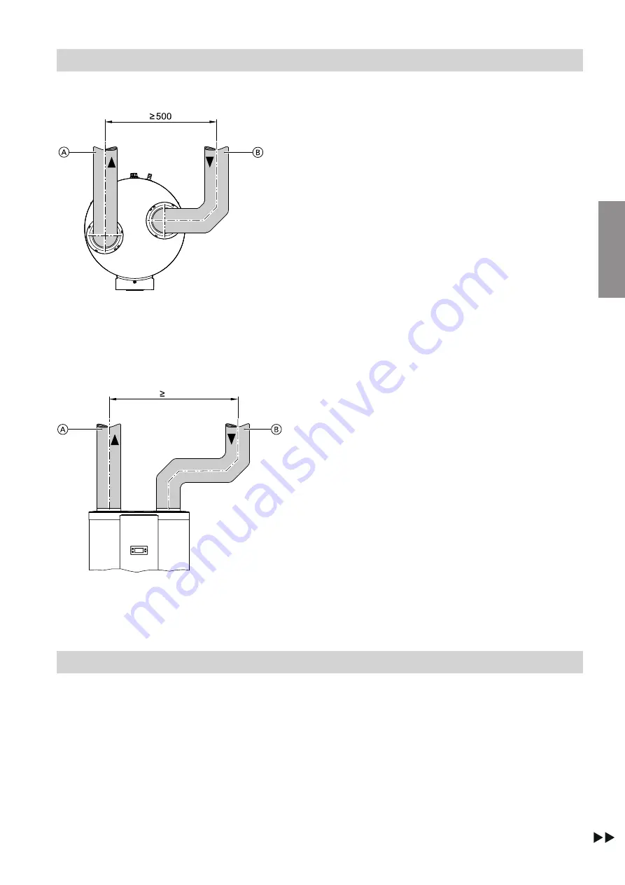
Air intake and air discharge duct through the wall
Fig. 12
A
Air discharge
B
Air intake
Air intake and air discharge duct through the roof
1000
Fig. 13
A
Air discharge
B
Air intake
Installation sequence
1.
Join individual duct sections together with connec-
tion pieces or female connections (see system dia-
gram on page 15).
!
Please note
Drilling swarf can cause faults in the DHW
heat pump.
Never allow drilling swarf to fall into the
DHW heat pump air intake aperture or air
discharge aperture.
2.
Secure the connections with self-tapping screws or
blind rivets. Use shrink tape to make the connec-
tions airtight.
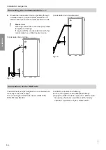
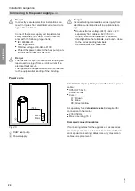
Connecting the condensate drain
When heating DHW, condensate forms on the inside of
the heat pump module. This condensate needs to be
routed via the condensate drain to a sewer.
1.
Secure the condensate drain hose to the conden-
sate drain connector with a hose clip.
!
Please note
Mechanical stress will damage the conden-
sate connection and may cause leaks.
Never twist the condensate drain connector
on the appliance.
2.
Route the condensate hose as a U-bend and con-
nect with a constant fall and a pipe vent to the pub-
lic sewage system or a neutralising system. If nec-
essary, connect to an on-site trap. Ensure that the
trap is connected securely.
Note
Connecting the condensate drain to rainwater
downpipes is not permissible.
3.
Check that the condensate can drain freely. Flush
the condensate drain if necessary.
Installation sequence
Conversion to outdoor air mode
(cont.)
6136003
Installation


