9
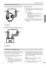
Overview of connections
802
907
1501
702
1755
Ø 631
160
73
927
1339
1397
1641
706
734
DN
DN160
46
187
187
46
H
,
K
,
L
,
N
,
O
A
B
M
R
D
C
E
F
G
R
A
B
P
O
N
H
P
Q
Fig. 2
A
Air discharge
B
Air intake
C
Programming unit
D
Heat pump control unit
E
Sensor well for draw-off profile L
Factory-fitted temperature sensors:
■
Cylinder temperature sensor
and
■
High limit safety cut-out for DHW heat pump
F
Sensor well for draw-off profile XL
G
■
Inspection port
■
Protective magnesium anode
■
Impressed current anode (accessories)
■
Immersion heater (accessory for type T0S-ze,
part of standard delivery for type T0E-ze)
H
Cold water/drain R
¾
K
Type T0S-ze only:
■
External heat generator:
Return G 1
■
Solar collector:
Return G 1 and threaded elbow (accessories) for
lower cylinder temperature sensor
L
Type T0S-ze only:
Flow of external heat generator/solar collector G 1
Preparing for installation
Preparing for installation
6136003
Installation


