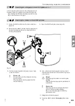
43
L
N
L
N
M
1~
N
L
M
1~
N
L
1,5 μF
4 μF speed2
speed1
L N
C1
C2
Θ
Θ
Θ
A
B
C
D
E
F
G
K
L
H
M
O
N
I
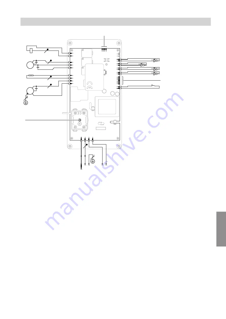
Fig. 34
A
High limit safety cut-out reset button, DHW heat
pump
B
Compressor
C
Immersion heater
or
External heat generator with switching relay
D
Switching output for fan
Speed 1 Slow (speed 1)
Speed 2 Fast (speed 2)
E
Diverter valve, defrosting
F
Signal lead for the photovoltaic system (multifunc-
tional relay)
G
Top cylinder temperature sensor (NTC 50 k
Ω
),
L = 750 mm (NTC1)
H
Air intake temperature sensor (NTC 50 k
Ω
),
L = 1500 mm (NTC2)
I
Bottom cylinder temperature sensor (NTC 50 k
Ω
),
L= 1150 mm (NTC3)
K
Evaporator temperature sensor (NTC 50 k
Ω
),
L = 1000 mm (NTC4)
L
Programming unit connection
M
Switching output for safety high pressure switch
N
Premium/economy tariffs
230 V~ Economy tariff
0 V~
Premium tariff
O
Internal power supply
Connection and wiring diagram
Connection and wiring diagram
6136003
Appendix


