Vitorond 200, VD2 Series 320 to 1080 Installation
5285 429 - 03
14
Assembly
Cast Iron Section Assembly
(continued)
IMPORTANT
For all sections, clean nipples with solvent and apply
supplied linseed oil.
IMPORTANT
During the entire compression procedure, all threads on
the draw tool assembly must be properly lubricated with
the supplied grease before use.
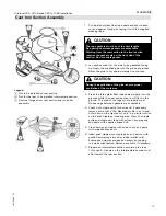
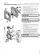
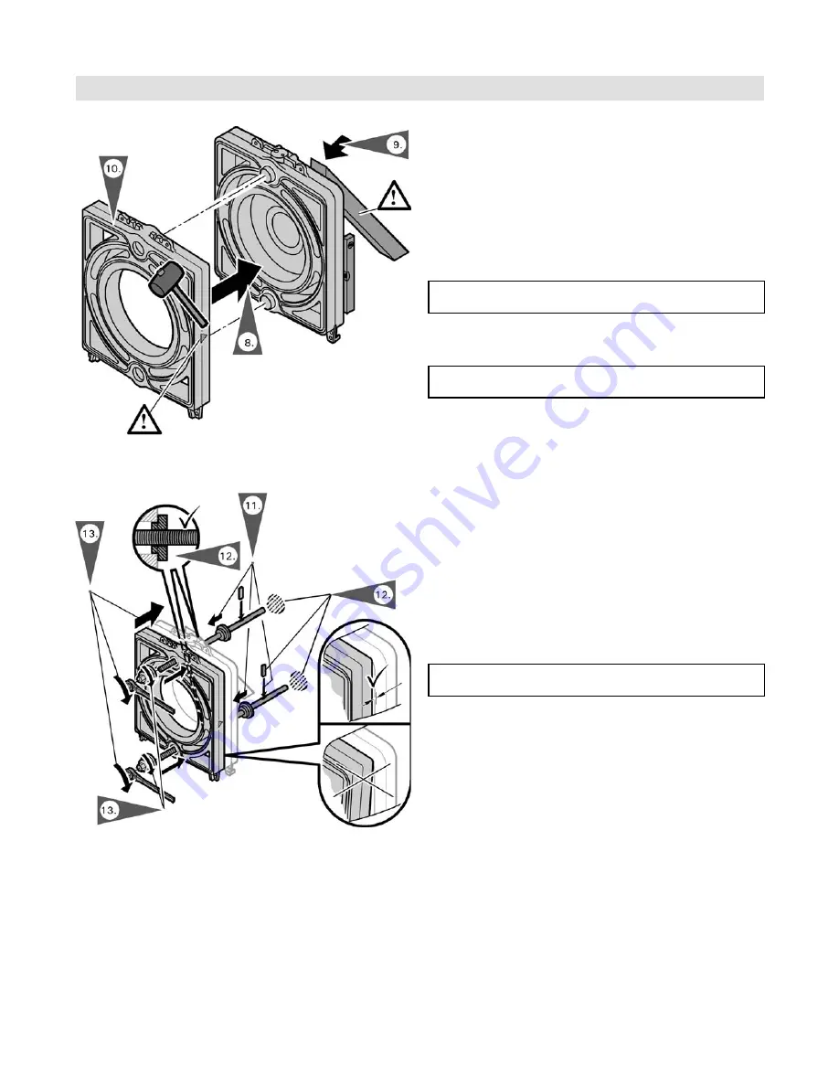
8. Align the prepared intermediate section with push
nipples of the rear section.
9. Lift the rear section onto the boiler foundation. Align
the section legs against the rear strip panel of the
boiler foundation (not shown). Properly position rear
section and secure against tipping.
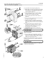
10. Mount intermediate section with wood or rubber
mallet by tapping it onto the push nipples of the rear
section. Do not hammer in place.
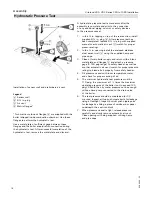
11. Insert the two main draw tool rods from the rear
section to the front section into the upper and lower
push nipple ports.
12. Slide pressure flanges onto the draw tool rods and
attach locking plates as shown.
13. Attach pressure nuts and align both parallel to each
other (same thread depth) by utilizing the ratchet
tool. Ensure that all sections are aligned parallel
to each other before applying pressure. Start to
tighten evenly. Once the push nipple ports touch,
do not apply further pressure. Do not use excessive
force if push nipple ports do not touch.
IMPORTANT
During the compression procedure, draw in only one
additional section at a time to prevent leaks at the joints.


