Boiler Control Alternatives
VITOROND 200, VD2A
19
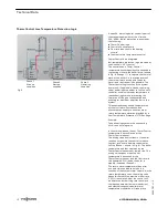
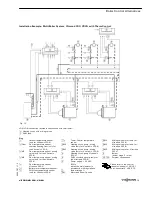
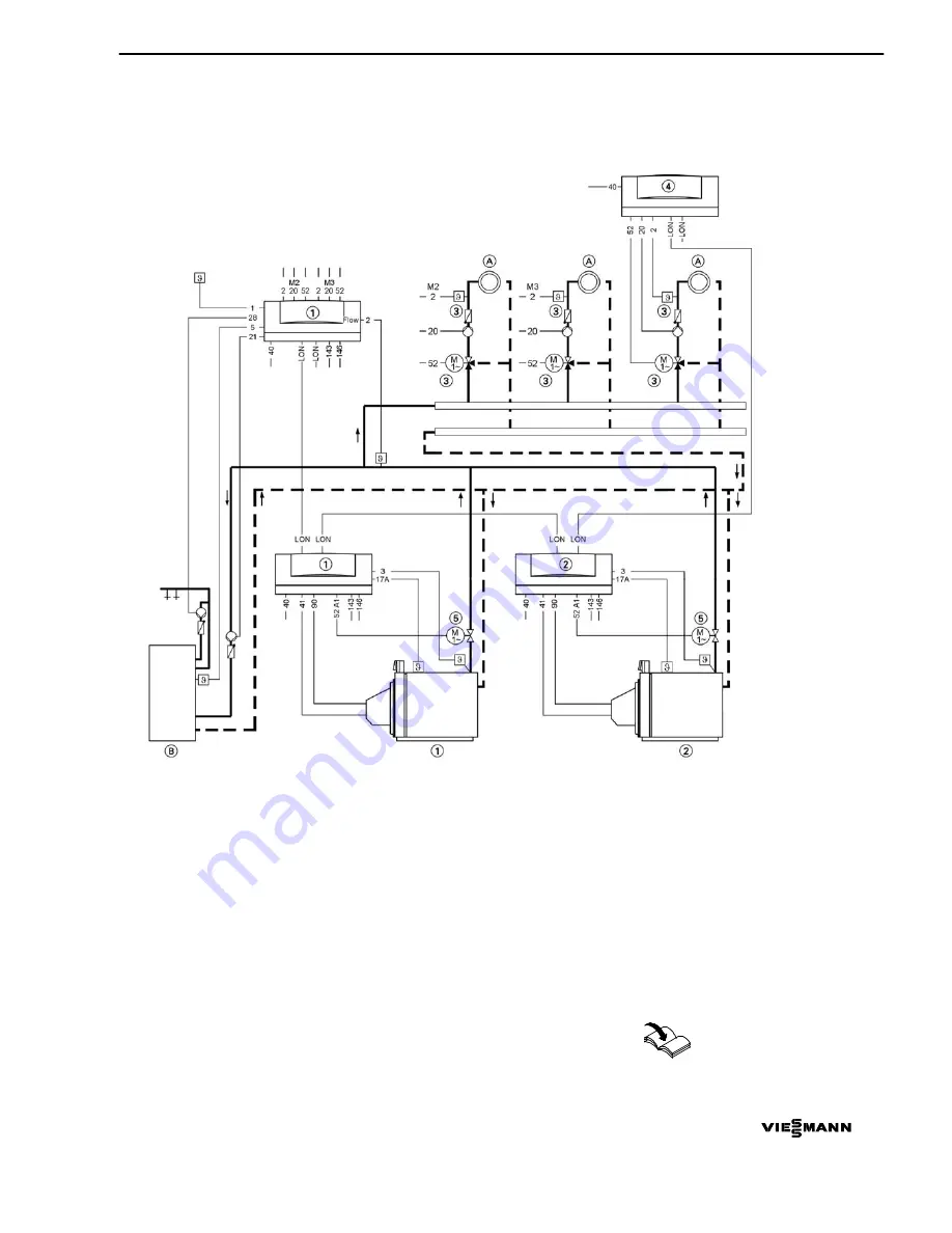
Installation Example: Multi-Boiler System, Vitorond 200, VD2A with Therm-Control
Fig. 13
LON LON connection (available connections with terminator)
A
Heating circuit with mixing valves
B
DHW tank
Plug
!
Outdoor temperature sensor
(only for Vitotronic 300-K)
?
Flow
Flow temperature sensor,
common heating flow (only for
the Vitotronic 300-K)
?
M2
Flow temperature sensor, mixing
valve (only for the Vitotronic
300-K)
?
M3
Flow temperature sensor, mixing
valve (only for the Vitotronic
300-K)
?
Flow temperature sensor
Vitotronic 200-H
§
Boiler water temperature sensor
%
DHW tank temperature sensor
(only for Vitotronic 300-K)
aJ
A
Therm-Control temperature
sensor
sÖ
M2
Heating circuit pump, mixing
valve (only for Vitotronic 300-K)
sÖ
M3
Heating circuit pump, mixing
valve (only for Vitotronic 300-K)
sÖ
Heating circuit pump Vitotronic
200-H
sK
DHW circulation pump (only for
the Vitotronic 300-K)
fÖ
Power supply, 120 VAC
60 Hz
Install the main isolator in
accordance with regulations
fA
Burner (stage 1)
gS
A1
Motorized butterfly valve
gS
M2
Mixing valve motor (only for
Vitotronic 300-K)
gS
M3
Mixing valve motor (only for
Vitotronic 300-K)
gS
M3
Mixing valve motor, Vitotronic
200-H
lÖ
Burner
(burner stage 2 / mod.)
aVD
/
aVH
External connections
Please refer to the control
manuals Vitotronic 100, GC1
and Vitocontrol-S, VD2/CT3.
5
3
5
4
7
8
7
v
1
.2

