20
Troubleshooting
Diagnosis (burner control unit LMO14. ...)
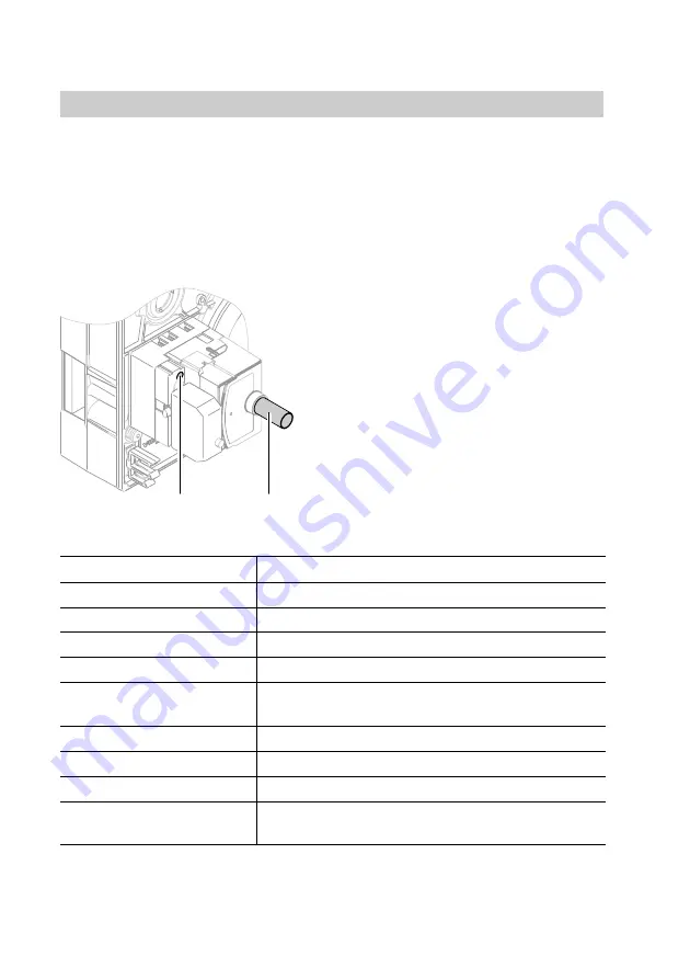
Function and fault indications by the indicator lamp (LED)
In standard mode, operating states are displayed by colour code through LED
indicator lamp
A
(see the following table).
The red indicator lamp stays on permanently after a fault shutdown. In this
state, the optical cause display may be activated (see flow chart on page21).
1.
Press reset button
B
for approx.
5s (longer than 3s).
2.
Then a flashing code appears.
The number of signal flashes
in one sequence indicates the
type of fault.
For explanations, see the table
on page22.
3.
To reset the burner and exit the
fault display, press the reset
button approx. 1s. (less than 3s.).
Colour of the LEDs
Operating condition
Constant yellow light
Oil preheater active, oil pre−heat time tw
Yellow flashing
Ignition phase pre−purge, ignition activated
Constant green light
Operation, flame steady
Green flashing
Operation, poor flame
Alternating flashing
yellowred
Undervoltage (
t
165V)
Constant red light
Fault, burner locked out
Red flashing
Fault display (for explanations see page22)
Alternating greenred
Extraneous light before burner start
Red flickering light
Interface diagnosis
For diagnostic with interface adaptor (accessory)
5692589GB
A
B
Summary of Contents for VEK
Page 31: ...31 Parts list Parts list cont 5692 589 GB 002 001 017 005 049 009...
Page 33: ...33 Parts list Parts list cont 5692 589 GB 047 020 041 021 040 80o 80p 034 033 046 039 038...
Page 37: ...37 Appendix 5692 589 GB...
Page 39: ...39 Appendix Maint service Maint service Maint service Maint service 5692 589 GB...
Page 41: ...41 Appendix Maint service Maint service Maint service Maint service 5692 589 GB...
Page 42: ...42 Appendix 5692 589 GB...


